Download

1 / 23
240 likes | 618 Views
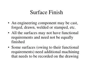
Surface Finish. An engineering component may be cast, forged, drawn, welded or stamped, etc. All the surfaces may not have functional requirements and need not be equally finished

E N D
Surface Finish • An engineering component may be cast, forged, drawn, welded or stamped, etc. • All the surfaces may not have functional requirements and need not be equally finished • Some surfaces (owing to their functional requirements) need additional machining that needs to be recorded on the drawing
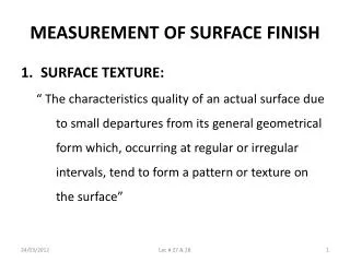
Surface Roughness The geometrical characteristics of a surface include, • Macro-deviations, • Surface waviness, and • Micro-irregularities. The surface roughness is evaluated by the height, Rt and mean roughness index Ra of the micro-irregularities.
Surface roughness number Represents the average departure of the surface from perfection over a prescribedsampling length, (usually selected as 0.8 mm) Surface roughness number (Ra) is expressed in microns. Ra = (h1+h2+-----+hn)/n The measurements are usually made along a line, running at right angle to the general direction of tool marks on the surface.
Actual profile, Af It is the profile of the actual surface obtained by finishing operation. Reference profile, Rf It is the profile to which the irregularities of the surface is referred to. it passes through the highest point of the actual profile. Datum profile, Df It is the profile, parallel to the reference profile .it passes through the lowest point B of the actual profile
Mean Profile, Mf • It is that profile, within the sampling length chosen (L) such that the sum of the material-filled areas enclosed above it by the actual profile is equal to the sum of the material void area enclosed below it by the profile. • Peak to valley height, Rt • It is the distance from the datum profile to the reference profile. • Mean roughness index, Ra • It is the arithmetic mean of the absolute value of the highest hi between the actual and mean profile. • Ra = 1/L ∫x=0 |hi| dx , where L is sampling length x=L
Measurement of roughness The roughness may be measured, using any of the following : • Straight edge • Surface gauge • Optical flat • Tool marker’s microscope • Profilometer • Profilograph • Talysurf
INDICATION OF SURFACE TEXTURE The basic symbol consists of two legs of unequal length inclined at approximately 60’ to the line representing the considered surface The symbol must be represented by thin line If the removal of material by machining is required, a bar is added to the basic symbol, If the removal of material is not permitted, a circle is added to the basic symbol. When special surface characteristics have to be indicated, a line is added to the longer arm of any of the above symbols, Basic symbol : only be used alone when its meaning is explained by a note
Indication of Surface Roughness The value or values defining the principal criterion of roughness are added to the symbols a- surface roughness value If it is necessary to impose maximum and minimum limits of the principal criterion of surface roughness, both values shall be shown maximum limit (a1) ;minimum limit (a2). Roughness a obtained by any production process Roughness a obtained by removal of material by machining Roughness a shall be obtained without removal of any material
If it is required that the required surface texture be produced by one particular production method, this method shall be indicated in plain language on an extension of the longer arm of the symbol Indication of machining allowance where it is necessary to specify the value of the machining allowance, this shall be indicated on the left of the symbols. This value shall be expressed in millimeters.
Generally to indicate the surface roughness, the symbol is used instead of value. The relation is given in following table.
Machining Symbols This symbol may also be used in a drawing, relating to a production process , to indicate that a surface is to be left in the state ,resulting from a preceding manufacturing process, whether this state was achieved by removal of material or otherwise
Position of the Specifications of the Surface Texture in the Symbol - The specifications Of surface texture shall be placed relative to the symbol as shown in figure.
If it is necessary to define surface texture both before and after treatment, this shall be explained in a suitable note or in accordance with figure The direction of lay is the direction of the predominant surface pattern, ordinarily determined by the production method employed. If it is necessary to control the direction of lay, it is specified by a symbol added to the surface texture symbol
Surface finish grade is shown Surface finish value is shown