Download
1 / 21
210 likes | 470 Views
Finite State Machines and Statecharts. Chapter 10 Part of Analysis Modeling. Designing Concurrent, Distributed, and Real-Time Applications with UML Hassan Gomaa (2001). Finite State Machines. Finite state machines are conceptual machines with a finite number of states.

E N D
Finite State Machines and Statecharts Chapter 10 Part of Analysis Modeling Designing Concurrent, Distributed, and Real-Time Applications with UML Hassan Gomaa (2001)
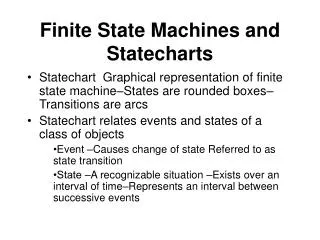
Finite State Machines • Finite state machines are conceptual machines with a finite number of states. • State transitions are changes in from one of these states to another.
Finite State Machines (cont) • State Machines consist of two basic elements: • Events: occurrences at a point in time. • States: recognizable situations that exist over an interval of time. • The dynamic aspects of the problem domain are modeled using finite state machines. • Typically one Object encapsulates one state machine.
Statecharts • In UML, state machines are represented in Statecharts. • Statecharts may be flat or hierarchical, and can depict a wealth of information regarding the expected operation of a system.
Conditions • Conditions are represented after an event with square brackets • Conditions determine which, if any, state the event transitions to.
Actions • Actions associated with a state transition are shown after the event causing that transition, separated by a “/”.
Activities • Activities actions appear on a states block using the “Do / Activity” notation. • Clean up the event transitions • Prevent unnecessary repetition
Entry and Exit Actions • Entry and Exit actions occur upon entering or leaving a state.
Entry and Exit Actions (cont) • Entry and exit actions can also be displayed as activities.
Hierarchical Statecharts • Hierarchies are used to simplify state charts. • Each sub-state gains the transitions of the super-state. • Being in the super-state means being in one and only one of the sub-states. • Common transitions can be aggregated to the super-state
Concurrent Statecharts • When multiple sub-states must be active simultaneously, a concurrent statechart is used.
Statechart Guidelines • States must represent identifiable situations or intervals of time. • Each state should have • A unique name. • An exit. • On flat statecharts, only one state at a time should be active.
Statechart Guidelines (cont) • Events and Actions are distinct: • Events are the cause of transitions • Something that happens. • Actions are the effect of transitions • A command. • Conditions are boolean values – they must evaluate to “true” or “false” • Actions, Activities, and Conditions are optional; use only where necessary.
Developing Statecharts from use Cases • Collect the actions, conditions and results from a use case description. • Develop a preliminary statechart with those actions and conditions as the events and the results and the states. • Consider any alternative external events not in the use case. • Develop hierarchical and concurrent statecharts as necessary.
Summary • Finite state machines are used to model the dynamic aspects of the problem domain using statecharts. • Statecharts consist of Transitions and States • Events cause Transitions (possibly based on a condition) • Actions or activities are caused by transitions. • Statecharts may be flat, hierarchical, or concurrent.