Download
1 / 44
480 likes | 699 Views
Applications of Silicon Detectors in Proton Radiobiology and Radiation Therapy. Reinhard W. Schulte Loma Linda University Medical Center. Outline. Introduction to proton beam therapy Applications of silicon detectors Proton radiography and computed tomography

E N D
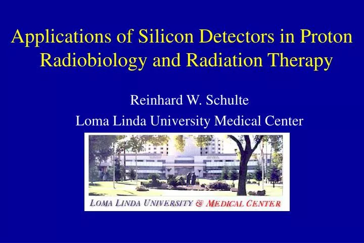
Applications of Silicon Detectors in Proton Radiobiology and Radiation Therapy Reinhard W. Schulte Loma Linda University Medical Center
Outline • Introduction to proton beam therapy • Applications of silicon detectors • Proton radiography and computed tomography • Particle tracking silicon microscope • Nanodosimetry
A Man - A Vision • In 1946 Harvard physicist Robert Wilson (1914-2000) suggested*: • Protons can be used clinically • Accelerators are available • Maximum radiation dose can be placed into the tumor • Proton therapy provides sparing of normal tissues • Modulator wheels can spread narrow Bragg peak *Wilson, R.R. (1946), “Radiological use of fast protons,” Radiology 47, 487.
Short History of Proton Beam Therapy • 1946 R. Wilson suggests use of protons • 1954 First treatment of pituitary glands in Berkeley, USA • 1956 Treatment of pituitary tumors in Berkeley, USA • 1958 First use of protons as a neurosurgical tool in Sweden • 1967 First large-field proton treatments in Sweden • 1974 Large-field fractionated proton treatments program begins at HCL, Cambridge, MA • 1990 First hospital-based proton treatment center opens at Loma Linda University Medical Center
Gantry beam line Hospital-based facility Fixed beam line 40-250 MeV Synchrotron LLUMC Proton Treatment Center
p p (a) p’ q e p (b) p’ p nucleus (c) p’ e g, n p nucleus (d) Main Interactions of Protons • Electronic (a) • ionization • excitation • Nuclear (b-d) • Multiple Coulomb scattering (b), small q • Elastic nuclear collision (c), large q • Nonelastic nuclear interaction (d)
Why Protons are advantageous • Relatively low entrance dose • (plateau) • Maximum dose at depth • (Bragg peak) • Rapid distal dose fall-off • Energy modulation • (Spread-out Bragg peak) • RBE close to unity
Combined measurement of position, angle and energy or LET of single particles High spatial resolution (microns) Wide dynamic energy range radiation hardness compatibility with physiological conditions of cells Why Silicon Detectors
Proton Treatment planning Proton radiography Proton computed tomography (CT) Proton Radiobiology Particle microscope Nanodosimetry Applications of Silicon Detectors
Proton Treatment Planning • Acquisition of imaging data (CT, MRI) • Conversion of CT values into stopping power • Delineation of regions of interest • Selection of proton beam directions • Design of each beam • Optimization of the plan
Computed Tomography (CT) • Faithful reconstruction of patient’s anatomy • Stacked 2D maps of linear X-ray attenuation • Electron density relative to water can be derived • Calibration curve relates CT numbers to relative proton stopping power X-ray tube Detector array
SP H Processing of Imaging Data SP = dE/dxtissue /dE/dxwater H = 1000 mtissue /mwater Relative proton stopping power (SP) CT Hounsfield values (H) Calibration curve Dose calculation Isodose distribution
CT Calibration Curve Stoichiometric Method* • Step 1: Parameterization of H • Choose tissue substitutes • Obtain best-fitting parameters A, B, C H = Nerel{A (ZPE)3.6 + B (Zcoh)1.9 + C} Rel. electron density Photo electric effect Coherent scattering Klein-Nishina cross section *Schneider U. (1996), “The calibraion of CT Hounsfield units for radiotherapy treatment planning,” Phys. Med. Biol. 47, 487.
CT Calibration Curve Stoichiometric Method • Step 2: Define Calibration Curve • select different standard tissues with known composition (e.g., ICRP) • calculate H using parametric equation for each tissue • calculate SP using Bethe Bloch equation • fit linear segments through data points Fat
Problems with the Current Method • Proton interaction Photon interaction • Multi-segmental calibration curve required • No unique SP values for soft tissue Hounsfield range • Tissue substitutes real tissues • Uncertainty requires larger range to cover tumor • Risk for sensitive structures
MWPC 1 MWPC 2 p Energy detector SC Proton Transmission Radiography - PTR • First suggested by Wilson (1946) • Images contain residual energy/range information of individual protons • Resolution limited by multiple Coulomb scattering • Spatial resolution of 1mm possible
Alderson Head Phantom Proton Range Uncertainties Range Uncertainties (measured with PTR) > 5 mm > 10 mm > 15 mm Schneider U. (1994), “Proton radiography as a tool for quality control in proton therapy,” Med Phys. 22, 353.
Proton Beam Computed Tomography • Proton CT for diagnosis • first studied for diagnostic use during the 1970s • dose advantage over x rays for similar resolution • not further developed after development of x-ray CT • Proton CT for treatment planning and delivery • renewed interest during the 1990s (2 Ph.D. theses) • fast data acquisition and proton gantries available • further R&D needed
Proton Beam Computed Tomography • Applications • Precise calculation of dose distributions • 3D verification of dose patient treatment position • tumor delineation without need of contrast media
Proton Beam Computed Tomography • Conceptual design • single particle resolution • 3D track reconstruction • Si microstrip detectors • p cone beam geometry • multiple beam directions • energy loss measurement • analysis of scattering and nuclear interactions SSD 3 SSD 1 SSD 2 SSD 4 ED p cone beam Trigger logic DAQ
Development of Proton Beam Computed Tomography • Experimental Study • two detector planes • water phantom on turntable • Theoretical Study • GEANT MC simulation • influence of MCS and range straggling • importance of angular measurements
Proton Treatment Planning Proton radiography Proton computed tomography (CT) Proton Radiobiology Particle microscope Nanodosimetry Applications of Silicon Detectors
dE/dx per mm D = 1 Gy RBE* n = 416 50 MeV protons 1.3 keV 36 ionizations 1.1 n = 112 10 MeV protons 4.7 keV 134 ionizations 1.4 n = 54 4 MeV protons 10 keV 276 ionizations 10 mm 2.0 * rel to 60 Co g rays Proton Radiobiology in Perspective
Study of Cellular Radiation Responses • in vitro (in glass ware): • single cell suspension seeded in culture flasks or Petri dishes • immortalized cell lines • exponential or stationary phase • in vivo (in a living organism): • tumor growth in animals • normal tissue response in animals (e.g., crypt cells) • response of microscopic animals (e.g., nematodes)
Dose 1 - 0.1 - S 0.01 - Study of Cell Survival in vitro • Study of cell survival in vitro • seeded cells are incubated for 3 - 14 days • ‘surviving cells’ form large colonies (> 50 cells) • surviving fraction is defined as • plating efficiency (PE) is defined as the fraction (%) of cells in an unirradiated culture that form colonies
Proton Treatment Planning Proton radiography Proton computed tomography (CT) Proton Radiobiology Particle microscope Nanodosimetry Applications of Silicon Detectors
l = 1.5 P(n) = ln/n! e-l Particle Tracking Silicon Microscope • Conventional radiobiological experiment • random traversal of cells by a broad particle beam • only average number of hits per cell is known • Particle-tracking radiobiological experiment • number of particles per cell is exactly known • broad beam or microbeam setup
Particle Tracking Silicon Microscope • Conceptual design • biological targets located on detector surface • single-particle tracking • energy or LET measurement • ASIC and controller design adapted to application • dedicated data acquisition system
Dose (Gy) 3.2 MeV protons Low-Dose Cell Survival • Low-dose studies with a proton microbeam • precise low-dose/fluence cell survival curves • hypersensitive region at low doses • more pronounced at higher proton energies (3.2 MeV vs. 1 MeV) Schettino et al. Radiation Res. 156, 526-534, 2001
--- expected -o- 6 hrs after priming g dose -- 6 hrs after priming g dose Adaptive Response & Bystander Effect • Low-dose studies with an alpha particle microbeam • only 10% of cells exposed • more cells inactivated than traversed (bystander effect) • previous exposure to low level of DNA damage increases resistance (adaptive response) Sawant et al. Radiation Res. 156, 177-180, 2001
Goals of the LLU/SCIPP Particle Tracking Microscope Project • Develop a versatile and inexpensive broad-beam and microbeam particle tracking system for • protons and alpha particles • wide range of energies (1 MeV - 70 MeV protons) • in vitro and in vivo radiobiological studies • research studies for radiation therapy and protection • support of DOE and NASA low-dose research programs
Proton Treatment Planning Proton radiography Proton computed tomography (CT) Proton Radiobiology Particle microscope Nanodosimetry Applications of Silicon Detectors
Loma Linda University Medical Center (1997) Weizmann Institute of Science (1997) UCSD (1998) Nanodosimetry Collaboration UCSC (2000) SCIPP
Single damage reparable charged particle 50 base pair DNA segment d electron Clustered damage irreparable ~2 nm Nanodosimetry Concepts • DNA is the principle target in radiobiology • Radiation interaction with DNA is a stochastic event • Single damages (break or base oxidation) are easily repaired • Clustered damages are difficult or impossible to repair
Conceptual Approaches Track Structure Imaging Single-Volume Sampling
l Mean Free Path versus Gas Pressure 1 Torr Propane (C3H8) • Mean free path: • n, targets per unit volume • s, interaction cross section • Assumptions: • same atomic composition • s is independent of density • Density Scaling: l = 1 / (n s) target projectile 1 mm in 1 Torr propane 2.4 nm in unit density material lgas = (rref / rgas) lref
SSD SSD E1 ions SV particle gas E2 vacuum trigger aperture Ion counter DAQ Ion Counting Nanodosimetry • Ionization volume filled with low-pressure gas • single particle detection • ion drift through aperture • wall-less sensitive volume • evacuated ion detection volume
E1 1 Torr 50mm e- particle ion Cathode E2 Intermediate vacuum High vacuum to pump 1 EM to pump 2 The Ion Counting Nanodosimeter Anode • Pulsed drift field • differential pumping system • electron multiplier • internal alpha source
E1 ions SV Particle detector gas E2 vacuum trigger aperture Ion counter DAQ Single Charge Counting • Ionization volume filled with low-pressure gas • single particle detection • ion drift through aperture • wall-less sensitive volume • evacuated ion detection volume
EM The Ion Counting Nanodosimeter Anode SSD1 SSD2 • Pulsed drift field • differential pumping system • electron multiplier • four SS detector planes for particle tracking and energy reconstruction E1 1 Torr 50mm e- particle ion Cathode E2 Intermediate vacuum High vacuum to pump 1 to pump 2
Nanodosimetric Spectra • ND spectra change with particle type and energy • average cluster size increases with increasing LET protons alpha carbon
Applications • New Standard of Radiation Quality in Mixed Fields • Radiation Treatment Planning: biological weighting factor • Radiation Protection: risk-related weighting factors • Manned Space Flight: Risk prediction (cancer & inherited diseases)
LLUMC Vladimir Bashkirov George Coutrakon Pete Koss WIS Amos Breskin Rachel Chechik Sergei Shchemelinin Guy Garty Itzik Orion Bernd Grosswendt - PTB UCSD - Radiobiology John Ward Jamie Milligan Joe Aguilera UCSC - SCIPP Abe Seiden Hartmut Sadrozinsky Brian Keeney Wilko Kroeger Patrick Spradlin Acknowledgements The nanodosimetry project has been funded by the National Medical Technology Testbed (NMTB) and the US Army under the U.S. Department of the Army Medical Research Acquisition Activity, Cooperative Agreement # DAMD17-97-2-7016. The views and conclusions contained in this presentation are those of the presenter and do not necessarily reflect the position or the policy of the U.S. Army or NMTB.