Download
1 / 17
170 likes | 326 Views
Noise Coupling in Focal Plane Arrays. Jacki van der Merwe MScEng Stellenbosch University. Outline. Focal Plane Arrays Receiver Noise Low Noise Amplifiers Introduction to Noise Coupling Calculating Noise Coupling Active Noise Figure and Noise Temperature Examples. Focal Plane Arrays.

E N D
Noise Coupling in Focal Plane Arrays Jacki van der Merwe MScEng Stellenbosch University
Outline • Focal Plane Arrays • Receiver Noise • Low Noise Amplifiers • Introduction to Noise Coupling • Calculating Noise Coupling • Active Noise Figure and Noise Temperature • Examples
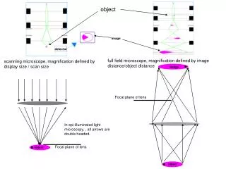
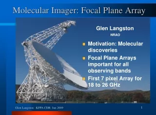
Focal Plane Arrays • Large, dense phased arrays of antennas • Placed in focal plane of reflector • In theory, any number of beams can be formed • Enables complete collection of the entire electric field in the focal plane of the reflector • Because they are densely packed, there exists a high level of mutual coupling between the element
Receiver Noise • Noise Temperature and Gain of the first element have the greatest effect on overall noise temperature of the system • Usually Low Noise Amplifier (LNA)
Low Noise Amplifiers (LNA) • Designed to add very little noise to system • Very Little ≠ None • Most of the noise travel toward the load • A small portion travels back toward the antenna and is radiated
Noise Coupling • Noise signals from LNA travel towards antennas and are radiated • Radiated noise are received by other elements and amplified • This is referred to as Noise Coupling
Calculating Noise Coupling • Represent coupled, noisy network as equivalent circuit diagram Direction of noise coupling
LNA Noise Model • Optimum Source Admittance (Ys=Ym) • Specific source admittance allowing for optimum noise match • Minimum noise Figure (Fm ) • Noise Figure resulting from optimum noise match • Equivalent Noise Resistance (Rn) • Representation in Ohm of the spectral density of a noise-voltage generator
Coupled Antennas • 2 Coupled Antennas at a time • All elements are identical, only coupling terms differ • Use superposition to calculate total coupling
Calculating Noise Coupling • Equivalent Circuit diagram now… Direction of noise coupling
Calculating Noise Coupling • Reduce Circuit diagram • Calculate noise power coupled to each element
Active Noise Figure and Temperature • Problem: If coupled noise is considered input noise, the input SNR is degraded, this results in false impression that the Noise Figure of the LNA improved. • All LNAs are seen as one “multiport LNA bank” • Add coupled noise from other LNAs in the bank to the noise power generated by the isolated LNA
Active Noise Temperature of 8x8 Vivaldi Array • Added noise temperature of 14 Kelvin • ≈ 9% of Isolated Noise Temperature • For SKA ≈ 1.3 K !!!