Download
1 / 28
280 likes | 481 Views
INPUT/OUTPUT ARCHITECTURE. By Truc Truong. Input Devices. Keyboard Mouse Scanner CD-Rom Game Controller. Output Devices. Monitor Printers Disk Drive Floppy Drive CDRW-Rom Speakers. Input and Output devices. Modem Network Interface Card Portable zip drives. Modem.

E N D
INPUT/OUTPUT ARCHITECTURE By Truc Truong
Input Devices • Keyboard • Mouse • Scanner • CD-Rom • Game Controller
Output Devices • Monitor • Printers • Disk Drive • Floppy Drive • CDRW-Rom • Speakers
Input and Output devices • Modem • Network Interface Card • Portable zip drives
Modem • What is a modem • It's short for MOdulator / DEModulator and it allows you to connect your computer to the phone line and communicate with another computer.
Data Transfer for Communication • Synchronous • In synchronous data transmission, data is sent via a bit-stream, which sends a group of characters in a single stream In order to do this, modems gather groups of characters into a buffer, where they are prepared to be sent as such a stream. In order for the stream to be sent, synchronous modems must be in perfect synchronization with each other. They accomplish this by sending special characters, called synchronization, or syn, characters. When the clocks of each modem are in synchronization, the data stream is sent.
Data Transfer for Communication • Asynchronous • In asynchronous transmission, data is coded into a series of pulses, including a start bit and a stop bit. A start bit is sent by the sending modem to inform the receiving modem that a character is to be sent. The character is then sent, followed by a stop bit designating that the transfer of that bit is complete.
Function of I/O modules 1) Control and Timing. 2) CPU Communicating. 3) Device Communication. 4) Data Buffering. 5) Error Detection.
Control and Timing 1) CPU asks I/O module to check the status of attached device. 2) I/O module tells the status. 3) CPU requests for data transfer to I/O module if device is ready. 4) I/O module gathers the data and transfers to the CPU.
Cpu Communication 1) Command Decoding : Like read/write seek etc. Data Exchange between CPU and Module. Status reporting to CPU, since peripherals are slow. Address recognition for the devices connected to it. 2) Device Communication : This may involves command, status information and data transfer. 3)Data Buffering : Essential function to overcome speed mismatch. 4) Error Detection : Like paper jam, bad data etc.
TECHNIQUES OF I/O 1) Programmed I/O : The CPU issues a command then waits for I/O operations to be complete. The CPU is faster than the I/O module then method is wasteful. 2) Interrupt Driven I/O : The CPU issues commands then proceeds with its normal work until interrupted by I/O device on completion of its work. 3) DMA : In this CPU and I/O Module exchange data without involvement of CPU. 4) Memory mapped I/O : Memory and I/O are treated as memory only. It means no signal like IO/M. 5) Isolated I/O : Address space of memory and I/O is isolated. It uses IO/M signal.
INPUT/OUTPUT CONTROLLERS Design Issues: There will be multiple devices that will generate interrupt signals. Consider the following when designing the I/O controllers 1) How does CPU knows which device has interrupted? 2) In case of multiple interrupt, which request is to beserviced?
Four design techniques 1) Multiple Interrupt Lines : In this method we have multiple lines like in IC 8085. 2) Software Polling : ISR polls to find out the device which has interrupted. The CPU reads a status register.The method is time consuming. 3) Daisy Chin : The method is hardware polling. The ack signal propagates through and is stopped by the device who is interrupted. 4) Bus Arbitration : In this method the device first gets control of bus and then raises an interrupt request for data transfer. The CPU issues an ack then the devices gives vector for branching.
Programmed I/O The code in the OS for Programmed I/O be more like: keyboard_wait: ; for get_ch test Keyboard_Status, 80000000h jz keyboard_wait mov eax, Keyboard_Data and display_wait: ; for put_ch test Display_Status, 80000000h jz display_wait mov Display_Data, eax This scheme is known as BUSY WAITING, or SPIN WAITING. The little loop is called a SPIN WAIT LOOP.
Problems with Programmed I/O *much time is wasted spin waiting. if it takes 100 instructions to program this, and each instruction takes 20ns to execute, then it takes 100 * 20nsec = 2000nsec = 2 usec to execute if a device takes 2msec (=2000usec) to deal with one character, then the percent of time spent waiting time waiting / total time = 2000us / 2000us +2us =99.9% We'd like a solution that spent less time "doing nothing"
Interrupts • CPU interrupt request line triggered by I/O devices • Interrupt handler receives interrupt • Maskable to ignore or delay some interrupts • Interrupt vector to dispatch interrupt to correct handler • Based on priorty • Some unmaskable • Interrupt mechanism also used for exceptions
Direct Memory Access • Special Purpose Processor: DMA controller • Free CPU from pure data transfer tasks • DMA access: Pointer to source, destination and size of data issued to start transfer • Processor writes the data DMA access data and continuous working • Handshake protocol • DMA request and DMA acknowledge • DMA controllers are standard components in PCs • Bus-mastering I/O hardware contain their own DMA hardware
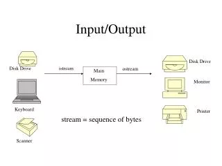
I/O Transfer Mode • Serial • In band signaling • Bit oriented • Bit/byte word translation • Parallel • Byte word oriented • Out of band signaling • IDE, SCSI
Serial Transfer • Asynchronous Clocking • Master clock the transfer • Slave derive clock from master • Synchronous clocking • Independent clocking • Verification by synchronization pattern
Parallel Transfer • Data transfer • Read sector • Write sector • Control • Disk seek • Transfer Integrity • Transfer parity • Data encoding