Download
1 / 21
260 likes | 573 Views
Inertial Measurement for planetary exploration: Accelerometers and Gyros. Bryan Wagenknecht bwagenkn@cmu.edu 3/30/2009. Significance of Inertial Measurement. Important to know “where am I?” if you’re an exploration robot Probably don’t have access to GPS or road signs to help you

E N D
Inertial Measurement for planetary exploration:Accelerometers and Gyros Bryan Wagenknecht bwagenkn@cmu.edu 3/30/2009 16-722: Accelerometers and Gyros for Navigation
Significance of Inertial Measurement • Important to know “where am I?” if you’re an exploration robot • Probably don’t have access to GPS or road signs to help you • Mass (inertia) is a property that holds regardless of environment (gravity or no) • Want to harness this for internal estimation of state (position and velocity) 16-722: Accelerometers and Gyros for Navigation
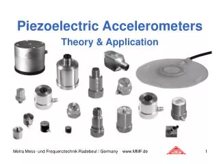
Physics and mechanical fundamentals: Accelerometers • Newton’s 3rd law F = ma --> F/m = a • Measure deflection of a proof mass: Δx • Known compliance of spring or cantilever beam gives you force: F = k Δx • Principles of transduction • Measure deflection via piezoelectric, piezoresistive, capacitive, thermal • Device types • Macro-sized (old-school) • MEMS: beam micro-machined from silicon wafer • Single- or multi-axis 16-722: Accelerometers and Gyros for Navigation
Physics and mechanical fundamentals: Gyroscopes • Precession: angular momentum conservation • Torque on spinning body results in torque about a 3rd axis • Precession torque generates signal to gimbal servos • Transduction: Magnetic induction “pick-offs” to determine angles between gimbal frames 16-722: Accelerometers and Gyros for Navigation
Physics and mechanical fundamentals: Gyroscopes • Coriolis force • Oscillating beam experiences in-plane rotation • Coriolis force causes perpendicular vibrations • Devices: piezoelectric gyro, hemispherical resonator gyro, MEMS gyro http://www.epsontoyocom.co.jp/english/special/crystal/sensing04.html 16-722: Accelerometers and Gyros for Navigation
Physics and mechanical fundamentals: Gyroscopes • Light interference • Laser light is split to travel opposite directions around a circuit • Rotation path length differences • Devices: ring laser gyro (RLG), fiber optic gyro 16-722: Accelerometers and Gyros for Navigation
Gimballed or Strapdown? • Strapdown units • No gimbals required (no gimbal lock!) • Smaller, lighter, can be cheaper • Problem: • Requires digital computing to accurately track vehicle orientation based on gyro readings • Gimballed units • Whole IMU mounted in gimbal frame • Vehicle orientation measurement is “easy” • Problems: • Errors grow near “gimbal lock” • Weight, power consumption, size, cost 16-722: Accelerometers and Gyros for Navigation
Bring it together: IMU • Sensor fusion • IMU gives you Δv and Δθ • Integrate readings (dead reckoning) • Problems • Accumulated error and drift • Noise • Gimbal lock • Changing gravity direction (as traveling over surface of a planet – affects accelerometers) • Temperature effects • Cost of accuracy 16-722: Accelerometers and Gyros for Navigation
Bring it together: IMU • Solutions • Calibration • Redundancy and skew (multiple IMUs) • Filtering (Kalman, traditional) • Schuler tuning (for gravity direction changes) • Realignment using visual markers/fixes • Combine with other sensors (GPS, compass, airspeed, odometer) • Built-in temperature sensor with analog circuitry for correction 16-722: Accelerometers and Gyros for Navigation
Homework: Underwater robot position estimation • We have a submersible robot with uni-directional thrusters at each end (rear and aft) and a 3-axis strap-on accelerometer (Crossbow CXL04GP3 – look up the specs here: www.xbow.com) mounted inside • It is executing a 30 sec. maneuver in a straight line using it’s thrusters • I’m providing you with the x-axis (aligned with direction of motion) voltage signal collected by the DAQ system for duration of the maneuver (collected at 100 Hz using a 16-bit analog-digital converter) • Integrate the signal (you need to convert it from volts back to m/s^2) to get an estimate of the robot’s position at the end of the 30-second maneuver. You may assume the accelerometer was properly calibrated and the robot starts from rest. • Given the noise in the signal (it’s uniform noise sampled within +/- the stated RMS noise range of the sensor), what is the uncertainty of your final position estimate? • Now imagine the robot executes the same maneuver in much colder water without re-calibrating the accel. first. Assume the zero-point of the accel. has drifted so that it now outputs 2.4 V at 0 g. Repeat Question 1 using the new zero-point. How does the accelerometer drift affect your position estimate? Comment (qualitatively) on the consequences of uncorrected accelerometer drift on the accuracy of your estimate. X-axis 16-722: Accelerometers and Gyros for Navigation
Historical applications • Originally developed for rockets/missiles (Robert H. Goddard) • Apollo missions used IMU with rotor gyros • Only used IMU for accelerated phases of mission • Align against stars during “coasting” phases • Star alignment allows for resetting of IMU and repositioning of gyro gimbal axes • Gyro errors build up quickly near gimbal lock • MUST AVOID GIMBAL LOCK 16-722: Accelerometers and Gyros for Navigation
Application: NASA Shuttles • Shuttles outfitted with 3 High Accuracy Inertial Navigation Systems (HAINS) from Kearfott Corp. • Redundant IMUs mounted at varied angles (skewed) • IMU contains rotor gyro on 4-gimbal frame and 3 accelerometers • 4 gimbals avoids gimbal lock • Alignment updates obtained from on-board star trackers 16-722: Accelerometers and Gyros for Navigation
Application: Mars Exploration Rovers (MERs) • MERs landed with two LN-200S units from Northrup Grumman • IMU contains 3 fiber optic gyros and 3 MEMS accelerometers • Experiences temperatures cycles -40 to 40 ˚C LN-200S IMU Weight: 1.65 lb Size: 3.5” dia x 3.35” h Operating range: Angular rate: ±11,459 deg/sec Angular accel: ±100,000 deg/sec^2 Accel: 70 g 16-722: Accelerometers and Gyros for Navigation
Other Applications • Aircraft navigation • Tactical missiles and smart munitions • Submarine/naval navigation • Spacecraft • Land travel (cars, robots, tractors) 16-722: Accelerometers and Gyros for Navigation
Companies that make IMUs • Military/Government Contractors • Honeywell (UAVs, missiles) • Northrup Grumman (MERs) • BAE (missiles) • Kearfott Corporation (NASA shuttles) • Civilian Applications • Crossbow • Analog Devices 16-722: Accelerometers and Gyros for Navigation
Example: Kearfott MOD VII Accelerometer triad assembly • 3 pendulum accelerometers (for 3-axis measurements) • Capacitive position detection • Old design (around for 40 years) 16-722: Accelerometers and Gyros for Navigation
Example: Crossbow GP-series MEMS accelerometer 4.45 cm 2.72 cm • 3-axis MEMS accelerometer • Light weight, small • Cheap: ~$150 2 cm CXL04GP3 Range: ± 4 g Bias: ± 0.1 g Noise: 10 mg (rms) Bandwidth: 100 Hz Operating temp: -40 to +85 Shock: 2000 g Weight: 46 grams 16-722: Accelerometers and Gyros for Navigation
IMU Comparisons 16-722: Accelerometers and Gyros for Navigation
Advancing the art… • Smaller, cheaper, faster computers for on-board computation • Advances in silicon manufacturing technology, MEMS • Improving MEMS accuracy • Integration of MEMS inertial sensors with CMOS chips 16-722: Accelerometers and Gyros for Navigation
Institutions and labs on cutting edge • MEMS research still ongoing, but accel. and gyro research is old news • CMU’s own MEMS lab involved in MEMS/single chip integration (circa. 2003) • Aerospace companies seem to be leading advances in extremely accurate IMU’s • MEMS labs developing small/cheap integrated IMU’s 16-722: Accelerometers and Gyros for Navigation
References • King, A.D. “Inertial Navigation – Forty Years of Evolution” <http://www.imar-navigation.de/download/inertial_navigation_introduction.pdf> • Inertial Measurement Unit Market 2007-2012 <http://www.electronics.ca/reports/mems/imu_market.html> • NASA Shuttle IMU Reference Guide <http://spaceflight.nasa.gov/shuttle/reference/shutref/orbiter/avionics/gnc/imu.html> • An integrated MEMS inertial measurement unitCardarelli, D.; Position Location and Navigation Symposium, 2002 IEEE, 15-18 April 2002 Page(s):314 - 319 • Hoag, David. "Considerations of Apollo IMU Gimbal Lock." Apollo Lunar Surface Journal (1963). NASA. <http://history.nasa.gov/alsj/e-1344.htm>. • Fraden, Jacob. Handbook of Modern Sensors, 2004 • Northrup Grumman datasheets <http://www.es.northropgrumman.com/> • Kearfott datasheets <http://www.astronautics.com> • Crossbow datasheets <http://www.xbow.com> 16-722: Accelerometers and Gyros for Navigation