Download
1 / 15
850 likes | 2.51k Views
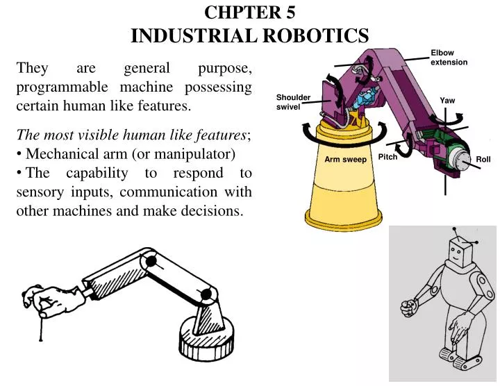
CHPTER 5 Industrial Robotics. Elbow extension. Shoulder swivel. Yaw. Pitch. Arm sweep. Roll. They are general purpose, programmable machine possessing certain human like features. The most visible human like features ; Mechanical arm (or manipulator)

E N D
CHPTER 5 IndustrialRobotics Elbow extension Shoulder swivel Yaw Pitch Arm sweep Roll • They are general purpose, programmable machine possessing certain human like features. • The most visible human like features; • Mechanical arm (or manipulator) • The capability to respond to sensory inputs, communication with other machines and make decisions.
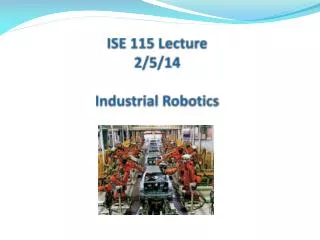
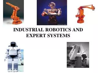
* While NC machines are designed for specific tasks; robots are designed for wider variety. The development of the robotics technology followed the development of the NC and they are quite similar; • They both involve coordinated control of multi-axes. • They both use dedicated digital computers as controllers. * Technical production applications of industrial robots include; spot welding, material handling, machine loading, spray painting and assembly. * Reasons for commercial and technological importance of industrial robots includes; It can be substituted for human in hazardous or uncomfortable work environments. Repeatability and consistency of the robot performance in the work cycle. It can be reprogrammed and equipped with necessary tooling system to perform different tasks. Robots are controlled by computers and can be connected to other computer systems to achieve computer integrated manufacturing.
1- ROBOT ANATOMY AND RELATED ATTRIBUTES Robot is constructed with a series of joints and links. Robot anatomy is concerned with the types and sizes of these joints and links and other aspects of the manipulator’s physical construction. 1-1 Joints and links Joint provides relative motion between two parts of body. Each joint provides the robot with a degree of freedom (D.O.F) of motion. Robots are often classified according to the total number of degrees of freedom (Most robots possess five or six degrees-of-freedom). Two links are connected to each joint (input link and output link). Links are the rigid components of the robot manipulator.
- Mechanical joints are classified into; Linear joint (L joint) translation motion. Orthogonal joint (O joint) translation motion. Rotational joint (R joint) rotational motion. Twisting joint (T joint) rotary motion. Revolving joint (V joint) rotary motion. - Each joint has a range over which it can be moved. The range for a translation joints is usually less than 1 m and for the rotational motion from as small as few degrees to as large as several turns.
1-2 Common Robot Configurations • Robot manipulator consists of two sections; • 1- Body-and-arm: for positioning of objects in the robot's work volume • 2- Wrist assembly: for orientation of objects. • 1- Body and arm assembly. With 3 D.O.F • There are 5 basic configuration commonly available in commercial industrial robot • Polar configuration • Cylindrical configuration. • Cartesian coordinate robot.
Jointed arm robot. SCARA (Selective Compliance Assembly Robot Arm), used for insertion type assembly operations. 2- Wrist assembly. With 2 or 3 D.O.F a) Roll: Rotational or swivel movement in a plane perpendicular to the end of the arm. b) Pitch: Rotational or bending movement in a plane vertical to the arm. c) Yaw: Rotational or twisting movement in a plane horizontal to the arm.
At the end of the wrist is a device (called end effectors) related to the task that must be accomplished by the robot. The end effectors is either, a gripper for folding or a tool for performing some process. The body and arm is for positioning of the end effectors while the wrist is for the oriented the end effectors. Joint notation system. Uses the joint symbols (L, O, R, T, V) to designate joint types used to construct robot manipulator. Separates body-and-arm assembly from wrist assembly using a colon (:) Ex.: TLR : TR
Examples • Notation TRL: (Polar Configuration) Consists of a sliding arm (L joint) actuated relative to the body, which can rotate about both a vertical axis (T joint) and horizontal axis (R joint). • Notation TLO: (CylindricalConfiguration) Consists of a vertical column, relative to which an arm assembly is moved up or down. The arm can be moved in or out relative to the column • Notation LOO: (CartesianConfiguration) Consists of three sliding joints, two of which are orthogonal. Other names include rectilinear robot and x-y-z robot.
Work volume (work envelope); Is defined as the envelope or space within which the robot can be manipulate the end of its wrist. It is determined by the number and type of joints, the ranges of the various joints, and the physical size of the links. The shape of the work volume depends largely on the robot configuration. • 1-3 Joint Drive systems • Electrical (servomotors or stepping motors) • Hydraulic (greater speed and strength, but relatively low accuracy) • Pneumatic (limited to smaller robots). • - The drive system, position sensors (and the speed sensors if used), and feedback control system determined the dynamic response characteristics of the manipulator. • - Factors influence speed of motion are; weight of the object, and the precision with which the object must be located. • - Speed of response (the time required for the manipulator to move from one point in space to the next). • - Stability, refers to the amount of overshoot and oscillation that occurs in the robot motion at the end of the arm. • The greater stability has slower in their response.
2- ROBOT CONTROL SYSTEMS • Each joint has its own feedback control system, and a supervisory controlled coordinates the combined actuation of the joint according to the sequence of the robot program. • Robot controllers can be classified into; • Limited sequence control, used only for simple motion cycles such as pick and place operations • Playback with point to point control • Playback with continuous path control, it capable to one or both; • Greater storage capacity. • Interpolation calculations • Intelligent control. • Interact with the environment. • Make a decision when things go wrong during the work cycle. • Communicate with humans. • Make computations during the motion cycle. • Respond to advantage sensor inputs such as machine vision.
3- END EFFECTORS • Grippers • Owing to the variety of the part shape, size and weight grippers must be custom designed. a- Mechanical grippers • Dual grippers • Interchangeable fingers • Sensory feedback • Sensing the presence of work part • Applying a specific limited force to work part. • Multiple fingered grippers • Standard gripper products b- vacuum grippers. c- Magnetized devices. d- Adhesive devices. e- Simple mechanical devices. (as hooks and scoops).
Tools • Spot welding gun. • Arc welding tool. • Spray painting gun. • Rotating spindle for drilling. • Assembly tool (e.g., automatic screwdriver). • Heating torch. • Water jet cutting tool. • 4- SENSORS IN ROBOTS • Internal used to control position and velocity of the various joints. • Potentiometers and optical encoder. • External to coordinate the operation of the robot with other equipment in the cell. • Limit switch. • Tactile sensors, to determine whether contact is made • Touch sensors • Force sensors. • Proximity sensors (range sensors). • Optical sensors. • Machine vision
Other sensors; temperature, fluid pressure, fluid flow, electrical voltage, current, and various physical properties. 5- INDUSTRIAL APPLICATIONS Situations that tend to promote of robot for human labor are; Hazardous work environment for human. Repetitive work cycle. Difficult handling for human. Multi-shift operations. Infrequent changeovers. Part position and orientation . Applications; Material handling. Processing operations. Assembly and inspection.
6- ENGINEERING ANALYSIS OF INDUSTRIAL ROBOT • 1- Manipulator kinematics (previous course) • 2- Accuracy and Repeatability • Control Resolution; refers to the capability of the control and positioning system to divided the range of the joint into closely spaced points that can be identified by the controller (addressable points). • This depends on 2 factors; • Limitation of the electro-mechanical components that make up each joint link combination. • The controller’s bit storage capacity for that joint. • Both is the same as NC machine tool. • Repeatability; is a measure of the robot’s ability to position its end-of-wrist at a previously taught point in the work volume. • Accuracy; is a measure of the robot’s ability to position the end of its wrist at a desired location in the work volume.
51 sec. 1 w.p. 1 hr. [(60*60) sec.]x w.ps. Ex. A robot performs a loading and unloading operation for machine tool. The work cycle consists of the following sequence of activities: Every 30 workparts the cutting tools in the machine tool must be changed. This irregular cycle takes 3.0 min. to accomplish. The uptime efficiency of the robot is 97%, and the uptime efficiency of the machine tool is 98%, not including the interruptions for tool changes. Down time results from electrical and mechanical malfunctions of the robot, machine tool and fixture. These two efficiencies are assumed not to overlap. Determined the hourly production rate, taking into account the lost time due to changes and the uptime efficiency. Sol: Tc = 5.5+33+4.8+1.7 = 45 sec. Ttc = (3/30 min)*60 = 6 sec/ pc (lost time due to tool change/w.p.) Total time = 45 +6 = 51 sec. Production rate = 60*60/51 =70.6 pc/hr. Rp = 70.6 * 0.97 * 0.98 =67.1 pc/hr.