Download
1 / 25
250 likes | 437 Views
Status of the TPS Control System. Kuo-Tung Hsu NSRRC, Hsinchu, Taiwan. Taiwan Photon Source Project. TPS: Taiwan Photon Source 200 million USD project Accelerator system 150 MeV linac Booster synchrotron Circumference: 496.8 m Storage ring Nominal energy: 3 GeV

E N D
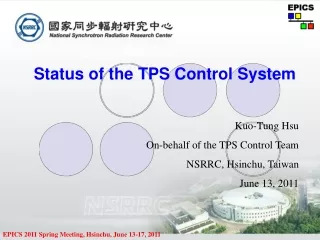
Status of the TPS Control System Kuo-Tung Hsu NSRRC, Hsinchu, Taiwan
Taiwan Photon Source Project • TPS: Taiwan Photon Source • 200 million USD project • Accelerator system 150 MeV linac Booster synchrotron Circumference: 496.8 m Storage ring Nominal energy: 3 GeV Circumference: 518.4 m • 24-cell DBA lattice – baseline design • Long Straight: 12 m x 6 (for long ID, injection, laser slicing, rf deflecting cavity..) • Standard straight: 7 m x 18 (for future chicane options) • Emittance less than 2 nm-rad in low emittance mode (distributed dispersion in ID straights) • Commissioning schedule ~ 2013
You Are Here Taiwan
Site of NSRRC TPS TLS
Taiwan Photon Source Project – cont. Aerial view Activity center & guest house TPS office TPS Service entrance Main entrance Utility building no.3 Service entrance Taiwan Light Source 1.5 GeV 120 m Dedication in 1993 North
Planning for the TPS Control System • Control system frame works => EPICS toolkit. • Commitment to the funding agency and budget consideration: Acquire as many of parts from local vendors as possible • => No VME related manufacture in Taiwan • (~ 35 VME crate system are used at Taiwan Light Source) • Give up VME/VME64x/… solutions for IOC layer. • => Adopt cPCI/PXI, AdvancedTCA, and another embedded solutions for IOC layer. • Borrow available resources from another labs. • Goals of 2008: Control system planning and refine the design. Setup EPICS test bed. Training EPICS staffs.
TPS Control System Infrastructure Signal Conditioning DB Server, Beam Physics Server, Alarm Server, AP Server, … etc. PC/Linux Storage Server Consoles and Servers Control Ethernet cPCI IOC aTCA IOC Embedded IOC IOC (Input Output Controller) • Embedded IOCs • Pentium/XScale/ARM/IXP/IOP Linux • Soft real-time system • GPIB/IEEE-488 Instruments • RS-232/422/485 Devices • CCD camera server • PLC (safety type system) • Bunch-by-bunch feedback system interface • Special applications PLC • Hard/Soft IOCs • - cPCI, aTCA IOCs • - Intel CPU/Linux (fully preemptive kernel ) • Hard/soft real-time • High volume I/O • High speed serial connection (GbE, … etc.) Safety Type System Network attached EPICS Devices (e.g. EPICS oscilloscope, … etc.)
Candidates of EPICS IOC - Hardware Building Blocks CompactPCI IOC (Linux) ACQ IOC (Linux) aTCA IOC (Linux) MOXA IOC (Linux) cPCI CPU board Intel IOP + ADC Compute Blade Intel XScale IXP RS232/422/485 Interface Switch Blade 128 Bits DI/DI DAC Libera IOC (Intel XScale, Linux) In Developing ADC DAC 128 Bits DI/DI Power supply, Network attached devices, Feedback engine In Developing BI, BO, AI, AO, Timing MRF’s EVG/EVR Network attached devices Custom Designed Power Supply Controller (~ 20 bit DAC performance) Main Power Supply BI, BO, AI, AO, Timing, Network attached devices
Software Environment • Control system framework: EPICS toolkit • High level physics applications: • => Depend upon machine physicists’ preference => Matlab/Accelerator Toolkit/Matlab Middle Layer another framework (e.g. XAL frameworks) is also in study => Setup virtual accelerator to support high level application development is in planning. • Many items are still in study • => Relation database • => Technical system interface • => Documentation, E-log • => Machine status broadcasting: web, IPTV, • … etc. • What are our major focus now: • We are no real experiences on EPICS => Do our best to increase slope of the EPICS toolkit learning curve. • Work out on device/driver support for various selected hardware..
Proposed Interface Standard cPCI I/O modules - 32/64/96 channel 16 bits AI (with transient signal capture capability) - 32 channel AO - 128 bit DI, 128 bit DO - EVG, EVR (cPCI & PMC form factor), Fine delay module - 32/64 channel 24 bits AI (with transient signal capture capability, in study) - 16 channel 20/21 bits AO (in study) - In house design electrical/optical fanout Main power supply control interface GbE interface, waveform support for the booster synchrotron main power supply Small power supply control interface GbE interface Feedback enable Booster energy ramping support (optional) Fast waveform capture Scope IOC Camera Firewire or GigE Vision
Proposed Interface Standard – cont. Ethernet and LXI Compliant devices Power supply (feedback enable) Diagnostics Electronics instruments, DMM, temperature, .. Motion control Ethernet based motion controller Interlock PLC RS-232C/422/482 devices Ethernet to RS-232/422/482 serial device servers or IOC GPIB/IEEE-488 LAN/GPIB gateway Miscellaneous Interface …
Possible Power Supply Control Interface If PSI type digital power supply is selected => Next Gen PSI power supply control interface (FOFB enable) Digital power supply #1 DPC - Dataconcentrator FOFB Link (Rocket I/O) Digital power supply #2 Control System Link (GbE link) Digital power supply #n Concepts of the PSI team
Possible Power Supply Interface – cont. Read Register Set Register PS #1 PS #2 PS #3 PS #4 PS #5 PS #6 PS #7 PS #8 PS #1 PS #2 PS #3 PS #4 PS #5 PS #6 PS #7 PS #8 Alternative Interface Solution for Small Power Supply Control (FOFB Enable) Configuration modules • Interface Mezzanine • Analogue and digital interface 20 Bit DAC 24 Bit ADC (> 18 bits ENOB) DI + DO Compact Flash System Ace EPROM Fast Corrector Setting (10 KHz rate, >> 10 kHz rate for booster corrector ramping) Single UDP/IP package working in multi-cast mode to control all fast correctors with address offset. PS module #1 Virtex V FPGA GbE Transceiver RocketIO Block PS module #2 PS Control (10 Hz rate) Batch Data Transfer (TCP/IP) GbE Transceiver RocketIO Block PPC Or MicroBalzer PS module #8 (16?) Trigger
Possible RF Control System Interface Control Console TPS Control Network Control Consoles * Control and monitoring * Status display * Conditioning & RF processing * Operation sequence * Data logger & browser * Alarm & reports * … etc. Ethernet Switch Fabric NSRRC Intranet SRF Cryogenic Plant Monitor and Archive PC SRF Cryogenic Electronics IOCs Signal Conditioning LHe level regulator LHe pressure regulator HEX gas flow regulator Master Oscillator Cryogenic Electronics Low Level RF System (LLRF) Cryomodule CESR type or KEKB type Transmitter PLC
Proposed Insertion Devices Control Interface TPS Control Ethernet ID gap/phase information To dedicated global compensation node (>100 update/sec) Insertion Devices IOC CompactPCI IOC (Linux) cPCI CPU board 128 Bits DI/DI 32 Ch ADC/ 16 Ch DAC Encoder update rate (100 ~ 200 Hz ?) Ethernet based Motion Controller Auxiliary Encoder Power Supply Interlock PLC Encoder Motor Driver Limit Switches
Proposed Superconducting Insertion Devices Interface TPS Control Ethernet Insertion Devices IOC 32 Ch ADC (10 kS/sec with average output) /16 Ch DAC CompactPCI (Linux) cPCI CPU board 128 Bits DI/DI MOXA RS-232/422/485 Serial Device Servers Coil current Liquid level Gas pressure Temperature Quench detection Beam current Cryogenic Electronics Temperature, LN2 Level, LH Level, … etc. Power Supplies Interlock PLC Quench Detector Remark: ADC with buffer and trigger capability to capture trip event for post-mortem analysis.
Turnkey System Interface • Many of turnkey systems compliant with EPICS based controls. • Possible turnkey systems included: • Linac • RF transmitter • Outsource insertion devices • Monochromator and other beamline components • ………. etc. • Possible turnkey EPICS devices included: • BPM electronics, Scope IOC, Motion control solution, … • Measures to minimize amount of workload for integration support and maintenance • Standard components should be chosen to get consistency of • hardware • EPICS development environment and documentation on the TPS application development process • TPS PV name convention
Proposed Linac Control Environment Local Controller (PLC, ..etc.) Local Controller (PLC, ..etc.) Local Controller (PLC, ..etc.) Local Controller (PLC, ..etc.) Local Control Panel Local Control Panel Local Control Panel Local Control Panel TPS Control Network EPICS OPI Diagnostic IOCs (Transient Digitizer,, FireWire or GigE Vision Camera, … etc.) + ADC/DAC (Optional) Event Receiver + Delay generator (Electrical, Optical Output) EPICS LXI Oscilloscope cPCI IOC DI/DI (Optional) cPCI CPU board CompactPCI IOC Fedora Core Linux or MontaVista Linux (real-time) TPS Control Environment Linac Control Ethernet Switch Modulator #3 RF Vacuum Interlock …etc. Gun Modulator #1 Modulator #2 Power Supply
Miscellaneous System Interface • Vacuum system • BI, BO, AI, AO, serial links, ..etc. • Diagnostics • BPM electronics: Ethernet. • BI, BO, AI, AO, counter • Machine protection • Dedicated PLC system with fast link • Ethernet to control system. • Personnel protection • Dedicated PLC system with fast link • Ethernet to control system. • Feedback system interface • …
Post-mortem Diagnostic Supports • BPM electronics: 16 k samples or more post-mortem buffer (turn-by-turn), dedicated fast data capture nodes to capture more than 5 seconds. • cPCI ADC module with post-mortem buffer: Up to 10 msec time resolution for more than 5 seconds. • Transient and waveform diagnostic: High timing resolution (~ nsec) with segmented sweep, multiple-trigger capability. • Beam trip trigger is planned to distribute via event system.
Works in Proceed • Cultivate EPICS peoples. • Define standard hardware, work out on EPICS Device/driver supports. • Define software standard (EPICS toolkit). • Planning for various issues (name convention, networking, …). • Setup test bed in 2008: Training system Pulse magnet control IOC K2 solid state modulator IOC (test) BPM system for TLS (gateway to TLS control system) Power supply control interface prototype Transient and waveform IOC Various EPICS clients applications RDBMS OPI • Work out a solid plans for the TPS control system: Limited budget, limited manpower, schedule …
Works in Proceed – cont. Setup EPICS learning system and test bed cPCI aTCA MicroIOC and Motion Controller MEDM Control Page 1 m EPU Targeted cPCI and aTCA platform in testing EPICS Training
Summary • The design of the TPS control system is on going. • All major components for control system are in intensive study. • Standardization hardware and software are the current focus. • EPICS toolkit training - a series training activities will be arranged. • Set up EPICS test-bed • Single kind of operating system solution for IOCs and consoles are preferred => Linux. • Economy design without scarify performances and reliability are the goals. • Select possible outsourcing items • Learn experiences from another labs • Help from the EPICS community is absolutely essential! Device/driver support, Timing system support, Control system infrastructure, Training, ... etc. Thank You for Your Attention!