Download
1 / 57
580 likes | 770 Views
Fuel Cell Design. Chemical Engineering Senior Design Spring 2005 UTC. Technical and Economic Aspects of a 25 kW Fuel Cell. Chris Boudreaux Wayne Johnson Nick Reinhardt. Technical and Economic Aspects of a 25 kW Fuel Cell. Chemical and Thermodynamic Aspects. Our Competence.

E N D
Fuel Cell Design Chemical Engineering Senior Design Spring 2005 UTC
Technical and EconomicAspects of a 25 kW Fuel Cell Chris Boudreaux Wayne Johnson Nick Reinhardt
Technical and EconomicAspects of a 25 kW Fuel Cell • Chemical and Thermodynamic Aspects Our Competence Investigate the design of --a 25 kW Fuel Cell --Coproduce Hydrogen --Grid parallel --Solid Oxide Electrolyte Not Our Competence
Outline Introduction to the project Process Description Process & Equip. Design Economic Analysis
Introduction Overall Reaction Methane + Air --> Electricity + Hydrogen + Heat + CO2
Introduction Gas Reformer Water SynGas Electricity Air Fuel Cell Heat POR Hydrogen Pressure Swing Adsorption Exhaust
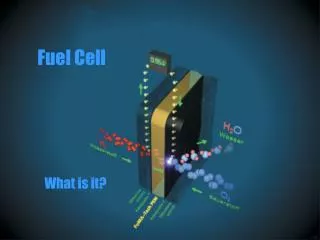
Fuel Cell-Chemistry SynGas POR H2 + CO H2 H2O CO2 CO O- O- “Air” Air O2 N2 Solid Oxide Electrolyte is porous to O-
Fuel Cell-Electricity Electrons SynGas POR H2 H2O CO2 CO Load O- O- “Air” Air O2 N2
Fuel Cell-Challenges SynGas POR H2 Hot SynGas + CO H2 H2O CO2 CO Recover H2 O- O- “Air” Air O2 N2 Hot Air Recover Heat
Desulfurizer (DS-101) • Removes trace amounts of Sulfur
Fuel Humidifier (FH-102) • 1.25 Kmol H20 per Kmol CH4 • Heat provided from combustor exhaust
Fuel Preheater (HX-103) • Heat provided from fuel cell POR exhaust
Reformer (R-104) • CH4 + H2O → CO + 3H2 (85%) • CH4 + 2H2O → CO2 + 4H2 (15%) • Heat provided from reaction in combustor
Combustor (COMB-105) • CH4 + 2O2 → CO2 + 2H2O (100%) • Necessary O2 provided from fuel cell air exhaust
Air Compressor (COMP-224) • Air intake for the system
Air Preheater (HX-223) • Heat provided by WGS exhaust
Water Gas Shift (WGS-222) • Consumes CO • CO + H2O → CO2 + H2 (72%)
Air Side Heat Recovery (HX-221) • Heat provided by combustor exhaust
Fuel Cell (FC-331) • CO + ½ O2 → CO2 (95%) • H2 + ½ O2 → H2O (60%) • DH to electricity = 50%
Fuel Exhaust Condenser (HX-443) • Condenses process water from exhaust gases
Chiller (Ref-446) • Provides cold water utility for HX-443
PSA Compressor (COMP-445) • Provides dried, compressed exhaust gas to the PSA system
Pressure Swing Adsorber (PSA-442) • Purifies hydrogen
Hydrogen Compressor (COMP-447) • Compressed hydrogen for sale
Water Purifier (WP-441) • Purifies process water
Water Pump (P-444) • Supplies water to fuel humidifier
Heat Exchangers • A=q/UFΔTlm • F = 0.9 • U = 30 W/m2°C • ΔTlm = (ΔT2 – ΔT1) / [ ln(ΔT2 / ΔT1) ]
Sulfur Purge 25°C 0.0002 kmol/hr H2S = 100% Desulfurizer Pure Natural Gas 25°C 0.33 kmol/hr CH4 = 100% Natural Gas Inlet 25°C 0.33 kmol/hr CH4 = 99.9% H2S = 0.001%
Fuel Humidifier POC Vent 26°C Pure NG 25°C 0.3 kmol/hr CH4 = 100% Humidified NG 273°C 0.67 kmol/hr H2O = 56% CH4 = 44% Area = 2.6 m2 q = 1.8 kW Recycled Water 5°C 0.37 kmol/hr H2O = 100% Cooled POC 283°C 3.51 kmol/hr N2 = 86% O2 = 9% H2O = 4% CO2 =1%
Fuel Preheater POR 850°C 1.3 kmol/hr H2O = 47% H2 = 29% CO2 = 23% CO = 1% Humidified NG 273°C Area = 6.3 m2 q = 5.3 kW Heated HNG 840°C Cooled POR 479°C
COMB-105 R-104 Reformer R-104 CH4 + H2O → CO + 3H2 CH4 + 2H2O → CO2 + 4H2 Depleted Air POC Pure NG SynGas Heated HNG q = 17 kW SynGas 734°C 1.26 kmol/hr H2 = 73% CO = 21% H2O = 3% CO2 = 2% Heated HNG 840°C 0.67 kmol/hr H2O = 56% CH4 = 44%
COMB-105 R-104 Combustor COMB-105 CH4 + 2O2 → CO2 + 2H2O Depleted Air POC Pure NG SynGas Heated HNG q = -17 kW Pure NG 25°C 0.03 kmol/hr CH4 = 100% Depleted Air 850°C 3.48 kmol/hr N2 = 87% O2 = 11% H2O = 2% POC 784°C 3.51 kmol/hr N2 = 86% O2 = 9% H2O = 4% CO2 =1%
Water Gas Shift Reactor CO + H2O → CO2 + H2 WGS Exhaust 480°C 1.26 kmol/hr H2O = 46.5% H2 = 30% CO2 = 23.2% CO = 0.3% Cooled POR 480°C 1.3 kmol/hr H2O = 47% H2 = 29% CO2 = 23% CO = 1%
Fuel Cell Depleted Air 850°C 3.48 kmol/hr O2 = 11.5% CO + ½ O2 → CO2 H2 + ½ O2 → H2O SynGas 750°C 1.26 kmol/hr H2 = 73% CO = 21% H2O = 3% CO2 = 2% POR 850°C 1.3 kmol/hr H2O = 47% H2 = 29% CO2 = 23% CO = 1% Heated Air 650°C 3.88 kmol/hr O2 = 21%
Pressure Swing Adsorber H Exhaust 25°C 0.38 kmol/hr H2 = 100% Air Inlet 25°C 0.13 kmol/hr Uncondensed Gases 5°C 0.68 kmol/hr H2 = 56% CO2 = 43% Purge 25°C 0.43 kmol/hr CO2 = 68%
Economic Components • Capital Costs • Operating Costs • Income Generated • Payback Period • Return on Investment
Capital Cost Assumptions • Cap Cost Program • Analysis, Synthesis, and Design of Chemical Processes • Compares to Peters and Timmerhaus • Stainless Steel