Download
1 / 21
210 likes | 380 Views
5-th DAMADICS Workshop Łagów, Poland, April 5th-7th, 2004. Sergej Jegorov, Piotr Wasiewicz. ACTUATOR BENCHMARK RESULTS: STEP I AND II. Presentation Plan. Control Valve Introduction Step I Step II Conclusions. Control Valve Introduction. Process Variable. CV – Control Value

E N D
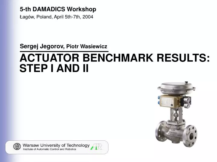
5-th DAMADICS Workshop Łagów, Poland, April 5th-7th, 2004 Sergej Jegorov, Piotr Wasiewicz ACTUATOR BENCHMARK RESULTS: STEP I AND II
Presentation Plan • Control Valve Introduction • Step I • Step II • Conclusions 5-th DAMADICS Workshop
Control ValveIntroduction Process Variable • CV – Control Value • Z – Valve Position • P1 – Valve Input Pressure • P2 – Valve Output Pressure • F – Medium Flow Rate Actuatorstructure 5-th DAMADICS Workshop
Considered models of control valve • servomotor rod movement model (1) • control valve model (2) • actuator model (3) • simplified model of the control valve (4) • simplified model of actuator (5) 5-th DAMADICS Workshop
Diagnostic Matrix (theoretical) Valve clogging Increased of valve or bushing friction Medium evaporation or critical flow Servo-motor's housing or terminals tightness Servo-motor's diaphragm perforation Rod displacement sensor fault Pressure sensor fault Positioner feedback fault Positioner supply pressure drop Unexpected pressure change across the valve Fully or partly opened bypass valves Flow rate sensor fault Valve plug or valve seat erosion Valve plug or valve seat sedimentation External leakage Internal leakage Valve clogging Servo-motor's spring fault Electro-pneumatic transducer fault Twisted servo-motor's piston rod r1 = Z – Z*(CV), (6) r2 = F – F*(Z, P1, P2),(7) r3 = F – F*(CV, P1, P2),(8) r4 = F – F*(Z),(9) r5 = F – F*(CV), (10) S1 = f(r1), (11) S2 = f(r2), (12) S3 = f(r3), (13) S4 = f(r4), (14) S5 = f(r5). (15) 5-th DAMADICS Workshop
FDI Structure FD using NN, FI using Fuzzy Logic 5-th DAMADICS Workshop
Search of Optimal NN Architecture • Transfer functions of all layers are logsig 5-th DAMADICS Workshop
Data Filtering filter2 filter1 filter3 5-th DAMADICS Workshop
NN Architecture Search. Training data without filtering net1 net2 net4 net3 5-th DAMADICS Workshop
Results achieved by applying filtering of measurements Blue – NN trained on filtr1 Red – NN trained on filtr2 Fault f4 Trained on filter1 but works on filter2 Fault f4 Trained on filter1 and filter2, but works on filter3 5-th DAMADICS Workshop
Time Diagrams of real and modeled signals. NN trained applying filter2, but examined using filter3 NNr2 NNr3 r2 res r3 res 5-th DAMADICS Workshop
Time Diagrams of real and modeled signals. NN trained applying filter2, but examined using filter3 NNr4 NNr5 r4 residual r5 residual 5-th DAMADICS Workshop
Measures of a Neural Networks "health" 5-th DAMADICS Workshop
Diagnostic Matrix (Practical) Valve clogging Valve plug or valve seat sedimentation External leakage Internal leakage Valve clogging Medium evaporation or critical flow Servo-motor's housing or terminals tightness Servo-motor's diaphragm perforation Servo-motor's spring fault Rod displacement sensor fault Pressure sensor fault Positioner feedback fault Positioner supply pressure drop Unexpected pressure change across the valve Fully or partly opened bypass valves Flow rate sensor fault . Valve plug or valve seat erosion Increased of valve or bushing friction Electro-pneumatic transducer fault Twisted servo-motor's piston rod 5-th DAMADICS Workshop
Fuzzification (Membership Functions) Input Membership Functions r1, r2, r4 Input Membership Functions r3, r5 • Sugeno Type • Defuzzificatiom method is whatever (wtaver) 5-th DAMADICS Workshop
Examples of results of isolation of fault 1 5-th DAMADICS Workshop
Examples of results of isolation of fault 3 5-th DAMADICS Workshop
Step I results (from forms S1-FF-fx) 5-th DAMADICS Workshop
Step I results (from forms S1-FF-fx) continued 5-th DAMADICS Workshop
Step II results 5-th DAMADICS Workshop
Conclusions • fault detection subsystem based on neural network technology was developed • fault isolation subsystem based on fuzzy logic technology was developed • Neuro-fuzzy FDI system is applicable for actuator fault diagnosis. Fault groups are distinguishable. • Close to 1, true fault detection rates factors achieved in Step I confirms acceptable NN models quality • High values of true fault isolation rates (Step I) confirms proper isolability features of fuzzy isolation scheme applied • Results achieved in Actuator Benchmark Step I are highly acceptable • The fault distinguishability problem exists because of limited availability of measurements when considering industrial benchmark Step II). In this case 6 fault groups are distinguishable. 5-th DAMADICS Workshop