Download
1 / 57
580 likes | 730 Views
Electrical Circuits. Electrical Circuits. Nearly all branches of electrical engineering are fundamentally based on circuit theory.

E N D
Electrical Circuits • Nearly all branches of electrical engineering are fundamentally based on circuit theory. • The only subject in electrical engineering that is more fundamental than circuit theory is electromagnetic field theory, which deals with the physics of electromagnetic fields and waves.
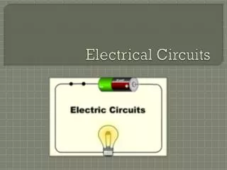
Electrical Circuits • The Ideal Basic Circuit Element • Has Only two terminal • It is described mathematically in terms of current and/or voltage • It cannot be subdivided into other elements • An electrical circuit may be defined as two or more Basic Circuit Elements interconnected by conductors.
Electrical Circuits • In electrical circuits, there are numerous types of electrical components such as resistors. capacitors. inductors, diodes, transistors, transformers, batteries, lamps. fuses, switches, and motors.
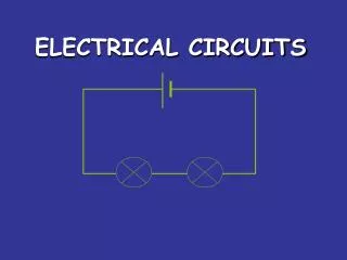
Electrical Circuits • Electrical circuits can be very simple. such as the circuit in a flashlight containing two batteries, a light bulb and a switch.
Electrical Circuits • The “conductors” that interconnect these components are usually wires or metal pathways integrated on a printed circuit hoard.
Electrical Circuits • Most electrical circuits. however, are much more complex than a flashlight. A standard television contains, among other things: power supplies, amplifiers speakers, and a cathode ray tube. • The microprocessor in a computer may contain the equivalent of millions of transistors interconnected in a single chip that is smaller than a fingernail
Electrical Circuits • The gravitational force is an attractive force that tends to move objects toward one another, the most common example being the earth’s gravitational force that attracts objects toward the center of the earth. Gravitational forces govern the motions of planets. stars, galaxies. and other celestial objects in the universe, and yet it is the weakest of all the natural forces. A type of force that is much stronger than gravity is electrical in nature.
Electric Charge • An electrical force is established between two charged particles. The force between the particles is attractive if the charges are unlike (i.e.. if one charge is positive and the other is negative). The force is repulsive if the charges are alike, that is. if both charges are either positive or negative. This force is referred to as an electrostatic force because the charges are static or stationary. The branch of electrical studies that deals with static charges is called electrostatics.
Like charges repel, unlike charges attract. The electric force acting on a point charge q1 as a result of the presence of a second point charge q2 is given by Coulomb's Law: Coulomb's Law
Electric Current • En electric circuit theory current is generally considered to he the movement of positive charges This convention is based on the work of Benjamin Franklin (1706—1790), who conjectured that electricity flowed from positive to negative. Today. we know that electric current in wires and other conductors is due to the drift of free electrons (negatively charged particles) in the atoms of the conductor.
Different Types of Current • Direct Current (DC) • Alternating Current (AC) • Others • Electric current is measured by means of an instrument called an ammeter. There are basically two types of ammeters: • analog and • digital.
Electric Potential Energy and Voltage • Potential energy can be defined as the capacity for doing work which arises from position or configuration. • Voltage is electric potential energy per unit charge, measured in joules per coulomb ( = volts). It is often referred to as "electric potential", which then must be distinguished from electric potential energy by noting that the "potential" is a "per-unit-charge" quantity.
Voltage Difference • The word difference denotes that voltage is always taken between two points. To speak of voltage “at a point is meaningless, unless a second point (reference point) is implied. A voltage exists across the positive and negative terminals of a battery.
Notation • Time varying quantities - lower case e.g. v(t), i(t) • sometimes assume time: v(t) = v • Time invariant quantities upper case e.g. V, R, • Remember to include units of measure e.g. 15 V, 7A
The passive sign convention • When we observe that positive current enters the positive terminal of a component, we say that the component obeys the passive sign convention (PSC). Therefore, when the passive sign convention is being obeyed, it indicates that a component is dissipating energy (or power) as charge is being displaced from a higher potential to a lower potential.
Resistance • Electrical resistance may be defined as an impedance to current flow through a circuit element. • All circuit elements, including even the conductors (wires) that connect them impede the flow of current to some extent.
Resistors Combinations • Resistance is measured by means of an instrument called an ohmmeter. Like ammeters and voltmeters that measure current and voltage, there are basically two types of ohmmeters: analog and digital. • An analog ohmmeter provides a resistance reading by means of a needle or pointer that moves across a calibrated scale. • Digital ohmmeters provide a resistance reading by displaying numbers in a window.
Example • Find the total resistance for the resistor circuit shown in the Figure
Suppose that we are designing a power-supply circuit. Our circuit design calls for a resistor that carries a direct current of 800 mA and has a voltage drop of 24 V. • What is the resistance of the resistor? • What power rating must the resistor have?
Independent Current and Voltage Sources • An independent voltage source is a two terminal circuit element, such as a battery or generator, that maintains a specified voltage between its terminals. The voltage is independent of the current through the element. • Because the voltage is independent of current, the internal resistance of the independent voltage source is zero. Actual voltage sources such as batteries do not have a zero internal resistance, but the internal resistance can be neglected it the resistance of the external circuit is large. • Thus, the independent voltage source is an idealization that simplifies circuit analysis.
Independent Current and Voltage Sources • An independent current source is a two-terminal circuit element through which a specified current flows. The current is independent of the voltage across the element. • Hence, like the independent voltage source, the independent current source is an idealization.
Example • The DC circuit shown in the Figure consists of a 10-V independent voltage source connected to two resistors in series. Find: • The current. • The voltage across each resistor, and • The power dissipated by each resistor.
Example • The DC circuit shown in the Figure consists of a 200-mA independent current source connected to two resistors in parallel. Find: • the voltage across the resistors and • the current in each resistor.
Nodes and Branches • A node is defined as a point of connection of two or more circuit elements. The actual node may or may not be a physical point where the conductors from two or more circuit elements come together. • Branch, an open path in a circuit including one or more circuit elements and no essential nodes
Short and Open Circuits • Short Circuit. • Basic Circuit element whose voltage is always 0. (Resistance =0) • Symbol • Open Circuit • Basic Circuit element whose current is always 0. (Resistance = infinity) • Symbol
Kirchhoff’s Laws • Kirchhoff’s current law (KCL): • The algebraic sum of all the currents at any node in a circuit equals zero. • Plumber’s Law • Kirchhoff’s voltage law • The algebraic sum of all the voltages around any closed path in a circuit equals zero • Roller Coaster Law
Example • For the DC circuit shown in the Figure, find the voltage across each resistor and the current in each resistor.