Download
1 / 17
170 likes | 303 Views
Object Oriented simulation of the Level 1 Trigger system of a CMS muon chamber. Claudio Grandi INFN-Bologna. Introduction. CMS Level 1 Trigger is implemented using custom designed hardware Why is L1 Trigger simulation important: test the hardware design

E N D
Object Oriented simulation of the Level 1 Trigger system of a CMS muon chamber Claudio Grandi INFN-Bologna Abstract B 029
Introduction • CMS Level 1 Trigger is implemented using custom designed hardware • Why is L1 Trigger simulation important: • test the hardware design • base to develop the High Level Trigger software • define data analysis strategies • (online monitoring of the hardware performances) • L1 Trigger simulation code has to be integrated with the CMS simulation and reconstruction programs! Abstract B 029
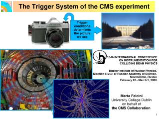
CMS detector at LHC Abstract B 029
ORCA and CARF • Object Reconstruction for CMS Analysis • see talk by D. Stickland • detector digitization • detector reconstruction • Level 1 trigger simulation • High Level Triggers software (HLT) • physics object reconstruction • analysis tools • CMS Analysis and Reconstruction Framework • see talk by V.Innocente • persistent storage of data • reconstruction and analysis framework Abstract B 029
Signal HEPEVT ntuples Zebra files with HITS CMSIM (GEANT3) MC Prod. Pile-up Catalog import Objectivity Database Objectivity Database ORCA Digitization (merge signal and pile-up) ORCA ooHit Formatter ORCA Prod. Catalog import Objectivity Database Level 1 Trigger simulation HLT Algorithms Reconstructed Objects Objectivity Database Objectivity Database ytivitcejbO esabataD HLT Grp Databases Mirrored Db’s (US,Russia,Italy...) Simulation for HLT studies Abstract B 029
L1 Trigger of a muon chamber The BTI finds segments in a quadruplet and assigns the bunch crossing using a mean-timer technique The TRACO builds tracks in a chamber correlating segments found in the R- view quadruplets The Trigger Server selects the 2 best segments, suppress ghosts and passes the tracks to the Regional Trigger Abstract B 029
Interface to end user System setup Configuration Geometry etc... Trigger components simulation L1 -trigger packages in ORCA Abstract B 029
Activate themselves when the trigger output is asked for Objects seen by the user Chambers and trigger units are in 1-1 correspondence Class diagram Abstract B 029
Action on demand • Modules register themselves at creation time and are invoked when required (implicit invocation architecture) • Use the Dispatcher-Observer pattern • System setup: L1MuDTTrigSetup is a LazyObserver<Run*> • Event processing: trigger components are LazyObserver<Event*> • Optimization of program flow. • User code very simple! Abstract B 029
Example of user code // Processing an event... L1MuDTTrigSetup* setup = Singleton<L1MuDTTrigSetup>::instance(); L1MuDTTrig* dttrig = setup->DTTrig(); //define chamber (iwh,ist,ise) and BX (is) intiwh=…;intist=…;intise=…;intis=…; L1MuDTChambPhSegm* first = dttrig->chPhiSegm1(iwh,ist,ise,is); L1MuDTChambPhSegm* second = dttrig->chPhiSegm2(iwh,ist,ise,is); L1MuDTChambThSegm* theta = dttrig->chThetaSegm(iwh,ist,ise,is); Abstract B 029
BTI simulation • More than 450 000 BTI chips in CMS, on average 35 are not empty in each event • do not instantiate BTI chips at setup time • instantiate BTI chips event by event if not empty • The BTI trigger cards (1 per chamber) keep: • map of active BTI chips (L1MuDTBtiChip) • vector of output BTI triggers (L1MuDTBtiTrig) • Reproduce the BTI behaviour as time flows: • run the BTI algorithm 26 times simulating the chip registers as they would appear before and after the expected triggering time Abstract B 029
When a new event is read in When output is asked for BTI interaction diagram Abstract B 029
TRACO simulation • More than 120 000 TRACO chips in CMS, on average 10 are not empty in each event • same situation as for the BTI’s • The TRACO trigger cards keep: • map of active TRACO chips (L1MuDTTracoChip) • vector of output TRACO triggers (L1MuDTTracoTrig) • Reproduce the TRACO behaviour as time flows: • run the TRACO algorithm 26 times using as input the BTI triggers found at the corresponding triggering time Abstract B 029
Trigger Server simulation • The Trigger Server chips are instantiated at setup time (250 for R- view and 250 for R-) • Reproduce the TS behaviour as time flows: • Algorithm is run 26 times using as input the TRACO triggers found at the corresponding triggering time • R- view algorithm implies a sorting of triggers: • example of use of bit-wise algebra: use ad hoc developed BitArray class for bit manipulation • sorting is done using BitArray::operator< • R- view algorithm is a bit packing of BTI’s output • use again BitArray methods Abstract B 029
Persistency • Persistency for MC information, raw data (including trigger) and reconstructed objects • Most CPU consuming processes are only run once! • For the Fortran part of the chain use ZEBRA • For the OO part of the chain use Objectivity/DB • see talk by L. Silvestris • All Objectivity/DB (and ZEBRA) access is via CARF interfaces • Use of Objectivity/DB is transparent to the simulation/reconstruction code and to the user program Abstract B 029
Persistency • Simulation is done in transient mode • Transition to persistent mode is done at the end of the event processing • Make a copy of the cache of the trigger card objects to its persistent representation • When reading from the DB CARF copies the objects to the memory • The corresponding C++ pointers are loaded into the cache of the trigger cards • Analysis is done in transient mode Abstract B 029
Summary • Object technology is well suited to reproduce the behaviour of the different electronic devices • use custom developed class for bit manipulation • OO code for L1 trigger simulation of a CMS muon chamber is fully integrated in ORCA, the CMS reconstruction and analysis program • uses reconstruction on demand • allows persistency in Objectivity/DB databases • Code already used in 1999 Monte Carlo production Abstract B 029