Download

1 / 20
200 likes | 268 Views
Defining protected-mode segment-descriptors. An example of a protected-mode bootsector application that draws a message to the video display. What will we do once there?.

E N D
Defining protected-mode segment-descriptors An example of a protected-mode bootsector application that draws a message to the video display
What will we do once there? • Let’s explore writing a bootsector program that will do something perceptible while in protected-mode, namely: show a message • We won’t be able to call BIOS functions (they’re designed to work in real-mode) • We must write directly to video memory
Recall PC Memory Layout RAM ROM-BIOS 0xF0000 0xC0000 VIDEO-BIOS VRAM 0xA0000 1-MB 0x00000
Three VRAM zones COLOR TEXT 32-KB 0xB8000 MONOCHROME TEXT 32-KB 0xB0000 GRAPHICS 64-KB 0xA0000
Array of picture-elements • Text-mode VRAM is organized as an array • Each array-element occupies one word • Word’s LSB holds ascii character-code • Word’s MSB holds a color-number pair 0 12 11 8 7 15 bgcolor fgcolor ASCII character-code nybble nybble byte
Color-Attribute Byte Blink R G B Intense G B R background color attribute foreground color attribute
Screen-element locations 80 columns characters 0..79 characters 80..159 25 rows characters 1920..1999 Video screen
x86 “Little-Endian” storage • Intel’s x86 CPUs use little-endian storage • The “little end” of any multibyte value is stored at the smaller operand-address • Example: EAX = 0x12345678 mov [0x9000], EAX 0x78 0x56 0x34 0x12 Memory-addresses occupied by operand 0x9000 0x9001 0x9002 0x9003
Drawing a character-string • Setup DS:SI with string’s starting address • Setup ES:DI with initial address on screen • Clear DF-bit (Direction Flag) in FLAGS register • Setup desired color attribute-byte in AH register again: lodsb ; next character to AL or al, al ; is final null-byte? jz finis ; yes, exit from loop stosw ; write char & colors jmp again ; go back for another finis:
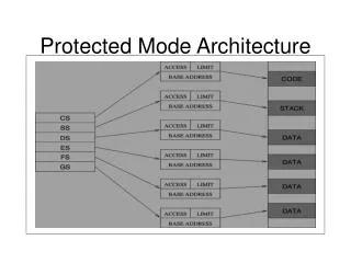
Planning our memory usage • To draw a screen-message in protected- mode, our program will need to address these memory-segments: • its code (executable, at 0x07C00) • its data (readable and writable, at 0x07C00) • its stack (readable, writable, expand-down) • the video ram (32KB, writable, at 0xB8000) • For its return to real-mode, our program will need 64KB code and data segments
VRAM segment-descriptor 31 16 Base[31..24] G D R S V A V L Limit [19..16] P D P L S X C / D R / W A Base[23..16] Base[15..0] Limit[15..0] 0 15 VRAM Base-Address = 0x000B8000 VRAM Segment-Limit = 0x07FFF (32-KB) Segment-attributes: P=1, A=0, S=1, X=0, D=0, W=1 DPL=0, G=0, D=0 (RSV=0, AVL=0) .WORD 0x7FFF, 0x8000, 0x920B, 0x0000
CODE segment-descriptor 31 16 Base[31..24] G D R S V A V L Limit [19..16] P D P L S X C / D R / W A Base[23..16] Base[15..0] Limit[15..0] 0 15 CODE Base-Address = 0x00007C00 CODE Segment-Limit = 0x0FFFF (64-KB) Segment-attributes: P=1, A=0, S=1, X=1, C=0, R=1 DPL=0, G=0, D=0 (RSV=0, AVL=0) .WORD 0xFFFF, 0x7C00, 0x9A00, 0x0000
DATA segment-descriptor 31 16 Base[31..24] G D R S V A V L Limit [19..16] P D P L S X C / D R / W A Base[23..16] Base[15..0] Limit[15..0] 0 15 DATA Base-Address = 0x00007C00 DATA Segment-Limit = 0x0FFFF (64-KB) Segment-attributes: P=1, A=0, S=1, X=0, D=0, W=1 DPL=0, G=0, D=0 (RSV=0, AVL=0) .WORD 0xFFFF, 0x7C00, 0x9200, 0x0000
STACK segment-descriptor 31 16 Base[31..24] G D R S V A V L Limit [19..16] P D P L S X C / D R / W A Base[23..16] Base[15..0] Limit[15..0] 0 15 STACK Base-Address = 0x00007C00 STACK Segment-Limit = 0x001FF (512-Bytes) Segment-attributes: P=1, A=0, S=1, X=0, D=1, W=1 DPL=0, G=0, D=0 (RSV=0, AVL=0) .WORD 0x01FF, 0x7C00, 0x9600, 0x0000
Setting up the GDT • Base-Address must be quadword-aligned .ALIGN 8 • NULL-Descriptor occupies first quadward theGDT: .WORD 0, 0, 0, 0 • GDT base-address and segment-limit: base: #0x00007C00 + #theGDT limit: 8 * (number of descriptors) - 1
Loading register LDTR BASE_ADDRESS LIMIT • We can load LDTR from our stack: mov eax, #0x00007C00 ; boot location add eax, #theGDT ; add GDT offset mov dx, #0x27 ; five descriptors push eax ; push bits 47..16 push dx ; push bits 15..0 lgdt [esp] ; load 48-bit LDTR add esp, #6 ; discard 3 words GDTR 48-bits
Entering protected-mode • No interrupts from any peripheral devices (since BIOS’s real-mode ISRs won’t work) • Set the PE-bit to 1 (in register CR0) • Do a far-jump (to load the CS attributes) • Load SS:SP with stacktop and attributes • Setup DS and ES for data and vram • Write character-string to video memory
Leaving protected-mode • Be sure segment-registers are loaded with selectors for descriptors that have suitable segment-limits and segment-attributes for correct execution when back in real-mode • Reset PE-bit to 0 (in register CR0) • Do a far-jump (to load CS with paragraph) • Load SS:SP with real-mode stack-address • Wait for user’s keypress before rebooting
Demo-program • We have a bootsector program on website (‘pmhello.s’) which illustrates the principles just discussed • Try assembling and installing it: • $ as86 pmhello.s –b pmhello.b • $ dd if=pmhello.b of=/dev/fd0 • Restart machine, use the GRUB memu to select this bootsector as execution-option
In-class exercises • What happens if you changed the ‘code’ descriptor’s access-rights byte from 0x9A to 0x9C (i.e., conforming code-segment)? • Where exactly in does the ‘expand-down’ stack-segment reside? • BASE_ADDRESS = 0x00007C00 • SEGMENT_LIMIT = 0x001FF