Download
1 / 32
320 likes | 468 Views
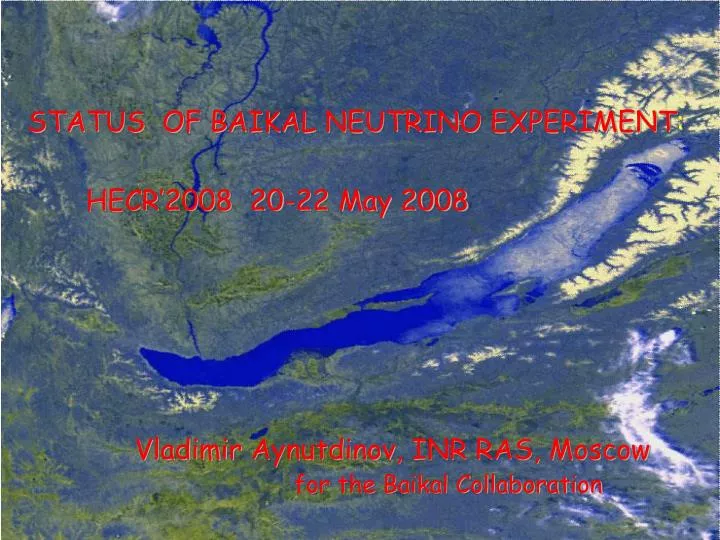
STATUS OF BAIKAL NEUTRINO EXPERIMENT :. HECR’2008 20-22 May 2008. Vladimir Aynutdinov , INR RAS, Moscow for the Baikal Collaboration. Collaboration Institute for Nuclear Research, Moscow, Russia. Irkutsk State University, Russia.

E N D
STATUS OF BAIKAL NEUTRINO EXPERIMENT: HECR’2008 20-22 May 2008 Vladimir Aynutdinov, INR RAS, Moscow for the Baikal Collaboration
Collaboration • Institute for Nuclear Research, Moscow, Russia. • Irkutsk State University, Russia. • Skobeltsyn Institute of Nuclear Physics MSU, Moscow, Russia. • DESY-Zeuthen, Zeuthen, Germany. • Joint Institute for Nuclear Research, Dubna, Russia. • Nizhny Novgorod State Technical University, Russia. • St.Petersburg State Marine University, Russia. • Kurchatov Institute, Moscow, Russia.
Outline: Introduction Neutrino telescope NT200 (1998 - 2003) Design and Physics Results (selected) Future Gigaton-Volume (km3-scale) detector BAIKAL-GVD Preliminary Design NT200 upgrade NT200+ (2005 - 2006) Prototype string for BAIKAL-GVD detector (April 2008) Summary Baikal
Baikal - History • Since 1980 Site tests and early R&D started • 1989/90 Proposal NT200 detector in lake Baikal submitted • 1993 NT36 started 13.4.93 (36 PMTs at 3 strings) The First Underwater Array First Neutrino Candidates • 1998NT200 commissioned 06.04.98 Start full Physics program • 2005/6NT200+ commissioned 09.04.05 • 2006/7 R&D for Gigaton (km3-scale) Volume Detector (GVD) • 2008 April 2008 - prototype string for GVD was installed
The Site 3600 m 1366 m NT-200 • 4 cables x 4km to shore. • 1070m depth Absorption length: ~25m Scattering length: 30-60 m Detection volume >> geometrical volume
Ice as a natural deployment platform Ice stable for 6-8 weeks/year: • Maintenance & upgrades • Test & installation of new equipment Winches used for deployment
Quasar : d = 37cm -8 strings: 192 optical modules 96 measuring channels T, Q measure *Timing ~ 1 nsec *Dyn. Range ~ 103 ph.e. Effective area: 1 TeV~2000m² Eff. shower volume: 10TeV~ 0.2Mt Height x = 70m x 40m, Vinst=105m3
Selected Results Low energy phenomena (muons) -Atmospheric neutrinos High energy phenomena (cascades) - Diffuse neutrino flux - Neutrinos from GRB - Prompt muons and neutrinos Search for exotic particles - Magnetic monopoles - WIMP
Atmospheric Muon-Neutrinos ETHR 15-20 GeV Skyplot of NT200 neutrino events for 5 years (galactic coordinates) 372 Neutrinos in 1038 Days (1998-2003) 385 events from Monte-Carlo
Atmospheric Muon-Neutrinos Lake Baikal (NT200) & South Pole (Amanda) CompleteskycoverageincludingcentralpartsofGalaxy Lake Baikal Skyplot of neutrino events South Pole
+ b + b WIMP Search Search of nearly vertically upward going muons, exceeding the flux of atmospheric neutrino produced muons Limits on the excess muon flux fromthe centre of the Earth as a function ofWIMP mass C + +
Search for fast monopoles N= n2 (g/e)2 N=8300 N (g = 137/2, n = 1.33) ~Em=107 GeV 90% C.L. upper limit on the flux of fast monopole (994 livedays) Event selection criteria: 1.Hit channel multiplicity Nhi t> 35 ch 2. Upward-going monopole (zi-z)(ti-t)/(tz) > 0.45 & o Background - atmospheric muons Amanda II (preliminary) Limit on a flux of relativistic monopoles: F < 4.6 10-17 cm-2 sec-1 sr-1
Search for extraterrestrial high energy neutrinos NT200 („BG“) NT200 is used to watch thevolume below for cascades. large effective volume Look for upward moving light fronts. Signal: Bright isolated cascades from neutrino interactions Background : Bremsshowers from h.e. downward muons
Diffuse Neutrino Flux Limits + Models Experimental limits +bounds/ predictions NT200 (1038 days) no statistically significant excess above the background from atmospheric muons has been observed The 90% C.L. “all flavour” limit (1038 days) for a =2 spectrum Ф~ E-2 (20 TeV < E < 50 PeV), and assuming e:: = 1 1 1 at Earth ( 1 2 0 at source ) E2 Фn<8.1·10-7 GeV cm-2 s-1 sr-1 (Baikal 2006)
Searching for diffuse neutrinos based on cascades reconstruction Cascade reconstruction: dlgE ~ 10%; dr ~ (5-10)%; dy ~ 5o Selection conditions: E>100 TeV, Nhit >18 Energy distribution of experimental (1999), as well as generated and reconstructed events from atmospheric muons Hit channel multiplicity Cut E>100 TeV old cut Expected limit (1038 days) for E-2 spectrum: E-2F ~ 4 ·10-7 GeV cm-2 s-1 sr-1 (twice lower than old one)
Ultimate goal of Baikal Neutrino Project: Gigaton (km3) Volume Detector in Lake Baikal NT200+/Baikal-GVD KM3NeT Antares Nestor Nemo • Deployment simplicity : ice is natural deployment • platform • Small background (bioluminescence) • Good water properties: Scatt. Length ~ 30-60 m • Abs. Length: ~25 m Amanda/IceCube
Sparse instrumentation: 91 – 100 strings with 12 – 16 OMs (1300 – 1700 OMs) - effective volume for >100 TeV cascades: ~ 0.5 -1.0 km³ dlg(E) ~ 0.1, dqmed< 5o - detects muons with energy > 10 - 30TeV Gigaton Volume Detector in Lake Baikal 208m 624m 70m 70m 120m 280m
NT200+ (2005) 36 additional PMTs on 3 far ‘strings‘ 4 times better sensitivity Improve cascade reconstruction Vgeom ~ 4 ·106 m3 Eff. shower volume: 104 TeV ~ 10 Mton Expected -sensitivity (3 yrs NT200+) E2 ФV< 2 · 10-7GeV cm-2 s-1 sr-1 Basic building block of Gigaton Volume Detector NT200+ = NT200 + 3 outer strings Detection system NT200+ is the same as NT200
Prototype string km3-scale BAIKAL telescope NT200+ current status Prototype string • Installation of a “new technology” • prototype string as a part of NT200+ • Investigations and in-situ tests of basic elements of km3 detector: new optical modules, DAQ system, cable communications. • Studies of basic DAQ/Triggering approach for the km3-detector. • Confrontation of classical TDC/ADC approach with FADC readout.
Basic string elements String control center 3 Optical Module (OM) 1 2 60 m (1) FADC sphere: 8-channel 12-bit 200 MHz FADC + Ethernet controller. (2) String PC unit: Data transmission and OMs control (3) LED Flasher unit: OM time and amplitude calibration 6 optical modules: 4 x PM XP1807 (Photonis). 2 x PM R8055 (Hamamatsu)
FADC unit Analog outputs of all 6 PMs are connected through coaxial cables with 8-channel 12 bit 200 MHz FADC board, located in the FADC unit. (two FADC channels are used to measure low-gain channels of two upper PMs) 3 1 2 OM power supply (12V) is provided through the analog cables (with possibility to switch on/off each individual module). String trigger is formed by the FADC controller: 1….4-fold majority trigger within coincidence window 10ns … 1 us.
String PC unit Data from the FADC are transmitted through an Ethernet line to the underwater micro-PC for on-line analysis and data-compressing. Communication between PC-unit and underwater control center of NT200+ is provided by DSL modems trough 2-wire line about 1 km length (twisted pair, now @ 2Mbps). 3 1 2 OM slow control and monitoring and LED flasher operation is provided by PC unit through RS-485 underwater bus. The main slow control functions are the regulation of PM high voltage, the control of LED flasher intensity and pulse delay, and the measurement of the PMT rates.
LED Flasher Time and amplitude calibration is provided by the string LED flasher unit. Light pulses from flasher are transmitted to each OM through plastic optical fibers with calibrated length. The LED flasher provides all relative time shifts, and allows to monitor the single electron spectrum of all PMs. 3 1 2 The LED flasher glass sphere also houses the low noise DC-DC converters for the OM power supply . DC-DC noise amplitude ~3 mV << A(1 p.e.) LED flasher parameters: - 2 independent LED - Pulse FWHM ~ 5 ns - Pulse delay between LED1/2 from 0…1000 ns (10 steps) - Pulse amplitude can be set from 1 to 200…1000 p.e. on PMs (~104 steps).
Optical Module (OM) • PMT: XP1807 (Photonis, ~12”) • R8055 (Hamamatsu, ~13”) • Divider 17 MOhm • Gain 3...5 x 107 • Preamplifier: Ka ~ 5 for high gain ch. • Ka ~1.5 for low gain ch. • HV unit: PHV12-2.0K DC-DC converter • VIP-2A (Irkutsk) converter 4. OM controller: microcontroller C8051F124 - RS-485 interface - PM pulse counter with regulated threshold - HV monitor - 2-LED calibration system (LED amplitude and pulse delay regulation, like in LED Flasher Unit).
Basic parameters of prototype string Number of optical modules: 6 Number of spectrometrical channels: 8 Type of PMT: XP1807 (12”), R8055 (13”) Dynamic range: high gain chan. 0.2 … ~100 p.e (*) low gain chan. 0.5 … ~300 p.e. Time window: 5 mks Time resolution: < 3 ns (*) – range of spectrometrical channel linearity
Prototype string installation (April 2008) First experience of the string installation: duration of string deployment ~5 hours including transportation from the shore center
Prototype string in-situ tests (LED flasher) PRELIMINARY ~20 m coax cable ~20 m LED flasher OM#1 Example of LED flasher event OM#2 A, V OM#3 5 2 4 6 OM#4 ~20 m coax cable ~20 m 1 OM#5 3 OM#6 Time shift estimation with LED flasher: time difference between neighbored OMs
Prototype string in-situ tests (Laser event) PRELIMINARY OM#1 OM#2 6 5 OM#3 1 2 OM#4 3 4 OM#5 OM#6 50 m Example of laser event with time shift correction LASER
Prototype string in-situ tests (muon events) PRELIMINARY OM#1 OM#2 OM#3 1 2 3 OM#4 OM#5 6 5 OM#6 4 Examples of down-going muon events Trigger: 3-fold coincidence
CONCLUSION 1. BAIKAL lake experiment is successfully running since 1993 - The First Underwater Array - First Neutrino Candidates - Some HE neutrinoproductionmodelsalready ruledoutbythe experiments 2. NEW configuration NT200+ starts work at April 2005 and is successfully operating now. -Improved cascade reconstruction - NT200+ gives good possibilities to optimise the design and to investigate the key elements of future Gton scale detector 3. Start R&D for Gigaton Volume (km3-scale) Detector (BAIKAL-GVD) - A “new technology” prototype string was installed: 6 OMs with 12”/13” - Preliminary in-situ tests of the prototype string with underwater laser, LED flasher and muons shows good performance of all string elements.
Estimation of the string time resolution (LED events) PRELIMINARY LED2 LED1 LED pulse fits (time estimation) LED1-LED2 delay distribution <Time resolution> ~1.5 ns in the range 5…100 p.e.