Download
1 / 44
450 likes | 548 Views
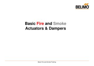
Fire Alarm Interface of Smoke Dampers. Presented by : Jason Lupa, PE Siemens Industry May 2018 Philadelphia, Pennsylvania. Objectives. Upon completion, participants will be better able to: Identify basic fire and smoke damper components

E N D
Fire Alarm Interface of Smoke Dampers Presented by: Jason Lupa, PE Siemens Industry May 2018 Philadelphia, Pennsylvania
Objectives Upon completion, participants will be better able to: Identify basic fire and smoke damper components Recognize damper applications and their fire alarm integration methods Learn the minimum code requirements along with industry best practices Damper testing & maintenance Know where to find additional information.
SLIDE DECK COMMENTARY CODE REFERENCES
What is the Purpose of a Damper? • To stop the spread of fire and smoke • Supply fresh air or remove smoke
Fire Damper – UL555 Fire dampers are actuated by heat Frame Fusible Link Blades Jackshaft Blade Damper
Fire Damper – UL555 Fire dampers do no require electric power and operate similar to a fire sprinkler head Frame Fusible Links Curtain Damper
Fire/ Smoke Damper - UL555S Smoke dampers are actuated by a smoke Combination fire/ smoke dampers are actuated by heat or smoke Motor Frame Blades with seals Actuator Jackshaft Blade Damper
Fire/ Smoke Damper - UL555S • UL555(S) requires 75 second closing time. • Test covers leakage, high velocity closing, other functions • Actuators are tested as an assembly with the damper, not listed alone. Actuator Smoke duct detector Blade Damper
Damper Classifications Static Rated Not tested with airflow through the damper. Installed in systems where the fans will shut off in the event of a fire. “Fan off System” Dynamic Rated Tested with heated airflow through the damper. A “fans on system” ─ these dampers will slam shut due to the spring loaded design.
Damper Summery Fire dampers are NOT actuated by the fire alarm system and are NOT part of a smoke management system. Fire Damper Smoke or Fire/ Smoke Damper Requires smoke detection!
Damper Locations • Smoke Barriers – divides a building into sections • Horizontal exit passageway enclosures • Atrium boundaries • Stairwell enclosures • Separations between occupancies in a mixed-use building • Smoke Partitions – usually encloses certain rooms • Storage rooms, trash rooms, boiler and furnace rooms, and similar rooms that have a higher-than-average chance of fire. • Shaft Enclosures • Typically when a duct travels vertically floor-to-floor. • Can be also be horizontal
Damper Exceptions Never installed in Type 1 grease, parking garages and clothes dryer exhaust systems (IBC ¶717.5.3). Never interfere with the operation of an engineered smoke exhaust system (such as for an atrium), approved alternate protection shall be used (IBC ¶717.2.1).
Damper Exceptions If ductwork crosses a rated wall, fire-rated gypsum board or a listed fire-wrap insulation material may be substituted for dampers Subducts may also be used vertical exhaust shafts. Continuous duct without openings in the rated corridor
Damper Exceptions A subduct may be used in place of a damper for some exhaust applications
NFPA 90A Application Detail A building may have a combination of dampers and alternative solutions. The Mechanical Engineer selects the smoke containment method. SMOKE DAMPER SUBDUCT SUBDUCT
Smoke Control Strategies The IBC Section 909 defines requirements for passive and active smoke control systems. The active smoke control system requirements are broken down into three methods: • Pressurization • Exhaust • Opposed airflow The Mechanical Engineer selects the types of smoke control method and locates the dampers. The Electrical Engineer designs the fire alarm interface equipment.
Smoke Control Strategies - Passive PASSIVE METHOD Passive methods of controlling smoke includes enclosing an area with smoke barriers, utilizing smoke doors and dampers at smoke barriers. For this method, smoke dampers close and isolate the fire. Air in the duct is static. Dampers
Smoke Control Strategies - Passive SHAFT DAMPERS PREVENT SMOKE FROM MIGRATING OUT OF FIRE ZONE INTO UNPROTECTED ZONES. If the HVAC fans are on, the fire alarm will override the environmental controls and close the dampers. If HVAC fans are off, typically dampers close but the fire alarm will prevent the dampers from opening.
Damper Control - Passive Standard application for closing dampers: normally powered when open; the fire alarm relay interrupts power to close. Status is not required. One fire alarm relay can control dampers individually or in groups.
Damper Control - Active ACTIVE METHOD Reopenable dampers can assist in exhausting dangerous amounts of toxic, low temperature smoke from the fire zone and to pressurize adjacent zones to prevent spread. For this method, some smoke dampers close while some open.
Damper Control - Active When part of a smoke control system, Dampers must be monitored for position and fault. Two fire alarm relays are required to force closed and force on. Within 3ft of actuator
Damper Control - Active supervised Un-supervised Fire Alarm System A SHORT DISTANCE REDUCES THE CHANCE OF A WIRE FAULT Component operating the emergency control function LISTED FIRE ALARM RELAY NFPA 72 21.2.5 21.2.6 21.2.7 21.2.8 3’ Emergency Control Function Interface Circuit NFPA 72 21.2.4 21.2.9 21.2.10 EXAMPLES SOME CONTROL DAMPER STAIR PRESSURIZATION ACTIVATION SMOKE CONTROL FAN CONTROLLER FACP Source: (pg.174 NFPA 72 fig A.3.3.137.1.1)
Damper Control - Active Smoke Control by FACP FACP must be UUKL listed FIREFIGHTERS SMOKE CONTROL PANEL Damper Status Fire Alarm Signal Damper Status FIRE ALARM CONTROL PANEL Damper Command STARTER Fire Alarm Signal Fan Command
Damper Control - Active Smoke Control by BMS Both FACP & BMS must be UUKL listed FIREFIGHTERS SMOKE CONTROL PANEL BMS Damper Status Purge FIRE ALARM CONTROL PANEL Fire Alarm Signal STARTER Damper Status Damper Command Fire Alarm Signal Fan Command Fan Status
Smoke Damper Activation Methods The IMC & IBC require one of the following smoke detection methods for a closing damper: Duct smoke detector Spot smoke detector above fire barrier doors Spot smoke detector near the air transfer opening Area smoke detection in corridor of damper Total coverage smoke detection for area served by the damper
Damper Activation: Duct Detector A duct smoke detector must be within 5 ft of the damper with no inlets or outlets between the detector and the damper
Damper Activation: Spot Detector A spot smoke detector must be within 5 ft of the damper with no inlets or outlets between the detector and the damper
Damper Activation: Spot Detector Large openings may require more than one detector Make sure the red dust covers are removed once system is online!
Damper Activation: Detector in Duct The smoke detector must be listed for this application and an access hatch must be provided. This method can be used for ‘zero flow’ applications. The damper may remain open even when the fan is off.
Access Dampers and smoke detectors must be accessible for inspection and testing. If they are not accessible from a grill or register, an access door in the ductwork is required.
Damper Activation: Detector Area Local damper detector coverage can be deleted if the dampers are controlled by area spot detectors. Corridor Coverage Area Coverage
Dampers and Smoke Detection FAQ’s Is damper smoke detection required to be connected to FACP? Yes, if a FACP is required, then both the IMC and NFPA 90A require the detectors to be installed in accordance with NFPA 72 and be connected to a fire alarm system. Do they cause an alarm condition? No. NFPA 90A and NFPA 72 state they are not required to activate the building evacuation alarm. IBC 907.3.1 states they shall report only as a supervisory signal unless the AHJ requires an alarm condition.
Sequence of Operations Consider effect of damper closure on HVAC system Consider effect of damper closure on smoke migration Code minimum vs something that works Engineered smoke control vs just damper control Fire Alarm vs BAS control
Damper Status Monitoring Open/ closed position status is required for active smoke control systems (IBC Chapter 9) and must report to a dedicated Firefighter’s Smoke Control Panel located in the Fire Command center. Local test switches are optional.
Damper Status Monitoring Position status is optional for passivecontaminent dampers (IBC Chapter 7). If provided, it may report to a central fire or BMS system, or it may be local, near the damper. Local test switches are optional. Status lights eliminate the need for visual inspections, so optional damper monitoring can reduce future inspection costs!
Who supplies the damper power
Smoke Damper Design Coordination Specifications should define who provides: • Dampers & Actuators: Div15. • Power & voltage: Div 16. • Smoke Detection • In-Duct detectors: Furnished & wired by Div 16, installed by Div 15. • Area detectors: Div 16. • Monitoring of the damper positions (status): Div 16
Referenced Codes & Standards • IMC section 606 • IBC section 907 • UL 864 Standard for Control Units and Accessories for Fire Alarm Systems • UL 555 Standard for Fire Dampers • UL 555S Standard for Smoke Dampers • UL 555C Standard for Ceiling Dampers • UL 263 Standard for Fire Tests of Building and Construction Materials • NFPA 72 National Fire Alarm and Signaling Code • NFPA 80 Standard for Fire Doors and Other Opening Protectives • NFPA 92 Standard for Smoke Control Systems • NFPA 105 Standard for the installation of Smoke Door Assemblies and Other Opening Protectives • Industry Specific, i.e. FGI/AIA guidelines for Healthcare
So Which One Applies? Codes are law • If you don’t comply with applicable codes, you won’t get an occupancy permit. Standards are voluntary • If code requires compliance with a particular standard, it is no longer voluntary. Guides and recommended practices • Industry best practices • Not required to use it • Information can end up in the codes • The Local AHJ has the final word so coordinate early and often!
Maintenance Testing IBC, IFC, & NFPA Requirements: Passive Containment Dampers (IBC Chapter 7) • Initial commissioning • End of first year after installation • Every 4 years after except in hospitals which is 6 years Active Smoke Control Systems (IBC Chapter 9) • Initial Commissioning • Dedicated systems – semi-annually • Non-dedicated systems – annually Verify these testing requirements with the Local AHJ and insurance provider to insure compliance.
Thank you for your attention! Presented by: Jason Lupa, PE Siemens Industry