Download
1 / 25
250 likes | 255 Views
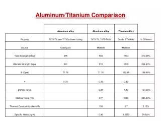
Federal Aviation Administration. Composite and Aluminum Wing Tank Flammability Comparison Testing. International Aircraft Systems Fire Protection Working Group Atlantic City, NJ November 17, 2011. Steve Summer

E N D
Federal Aviation Administration Composite and Aluminum Wing Tank Flammability Comparison Testing International Aircraft Systems Fire Protection Working GroupAtlantic City, NJ November 17, 2011 Steve Summer Federal Aviation AdministrationFire Safety Branch http://www.fire.tc.faa.gov
Overview - Wing Tank Flammability Parameters Flammability Drivers on Ground • Top skin and ullage are heated from sun • Hot ullage heats top layer of fuel, causing evaporation of liquid fuel • Bulk fuel temperature however, remains relatively low Flammability Drivers In Flight • Decreasing pressure causes further evaporation of fuel • Cold air flowing over the tank causes rapid cooling and condensation of fuel vapor in ullage • These concepts were observed during previous testing and reported on recently (see rpt #DOT/FAA/AR-08/8) • The objective is to now compare flammability progression in a wing fuel tank test article with both aluminum skin and composite skin with varying topcoats and thicknesses
Summary of Previous Results The results of initial testing have been documented in FAA report DOT/FAA/AR-11/6 and is available on the Fire Safety Branch Website • Initial testing consisted of bare composite and aluminum panels, as well as white-painted composite and black-painted aluminum. • Bare composite (black) resulted in significantly increased ullage temperatures, and therefore also higher flammability readings than the bare aluminum, however • Once airflow over the tank was initiated, temperature and flammability profiles behaved very similarly • When aluminum tank was heated sufficiently, and the starting temperature and flammability values were equivalent, the two tanks behaved very similarly.
Summary of Previous Results (cont.) • Topcoat color (white) applied to composite panel had little effect of tank temperatures and flammability levels. • Topcoat color (black) for aluminum panel had dramatic effect on tank temperatures and flammability profile, making it behave more like the composite. • The overall correlation of high THC measurements with high ullage temperature increases is further indication that ullage temperature changes are the driving force behind in-flight flammability for wing tanks. • This is contradictory to how the Fuel Tank Flammability Assessment Method calculates flammability exposure
Current Tests • Tests with a white topcoat color applied to the aluminum panels, to provide a further direct comparison of aluminum/composite fuel tank flammability. • Panel Heat Tests • Wind Tunnel Tests • Tests with varying thickness composite panels (¼″ to ¾″) to analyze the effect on tank flammability. • Panel Heat Tests • Wind Tunnel Tests
Current Tests (cont.) • 727 wing surge tank test article has been re-skinned with composite material and placed alongside aluminum 727 wing surge tank. • Testing conducted to compare tank flammability of aluminum and composite 727 wing surge tanks under actual solar radiative heating.
Test Apparatus – Panel Heat Tests • Test panels statically heated to examine the heat transfer through each panel. • Test panel placed in rack with three radiant heaters placed 12” above. • Heated for 20 minutes, followed by a 25-minute cool-down period. • Center-point temperature on bottom surface recorded.
Test Apparatus - Wing Tank Test Article • Constructed wing tank test article from previous test article • Interchangeable aluminum and composite skin panels on top and bottom with an aerodynamic nose and tail piece • Tank is vented and has a gas sample port for THC analysis, pressure transducer, and an extensive array of thermocouples • Radiant panel heaters used to heat top surface to simulate ground conditions
Test Apparatus – Airflow Induction Test Facility • Subsonic induction type, nonreturn design wind tunnel • Induction drive powered by two Pratt & Whitney J-57 engines
Test Apparatus – Airflow Induction Test Facility • Test article was mounted in the high speed test section • 5-½ foot in diameter and 16 feet in length. • Maximum airspeed of approximately 0.9 mach, though with the test article we measured airspeeds of approximately 0.5
Test Apparatus – Airflow Induction Test Facility • Due to the design, a simulated altitude (i.e. reduction in pressure) is observed as the airspeed is increased.
Test Conditions – Airflow Induction Test Facility • Fuel levels of 40, 60, 80% were examined • Radiant heaters used to heat top surface of tank for 1 hour prior to fueling • Fuel was preconditioned to 90F and transferred into the tank • Heating of tank was continued for 1 hour at which point heaters were removed and wind tunnel was started. • Engines initially run at idle for 5-10 minute warm up period and then taken to 90% throttle • 90% throttle position maintained for a period of 30 minutes • Discrete THC sample points were taken throughout testing
Air Induction Facility Test Results – 80% Fuel Load, Low Heat Setting
Air Induction Facility Test Results – 40% Fuel Load, High Heat Setting
Air Induction Facility Test Results – 80% Fuel Load, Low Heat Setting
Air Induction Facility Test Results – 80% Fuel Load, High Heat Setting
727 Wing Tank Test Articles • Last 8 feet of each wing removed, upper panel covering entire surge tank of left wing removed, and re-skinned with an 1/8″ thick composite panel. • Each surge tank instrumented with 12 thermocouples and THC sample line. • Capacity of tank ~ 36.5 gallons • Each tank was filled with 25 gallons of JP-8 fuel and allowed to heat/cool according to ambient conditions of the day.
Conclusions • White topcoat, and black topcoat applied to aluminum panels (previous testing) both resulted in tank temperatures and THC measurements consistent with composite fuel tank. • This is evidence, that the differences seen in previous results was not due to differences in property materials, but was rather due to the reflective behavior of the bare aluminum material. • Panel heat tests with composite panels of varying thickness showed that the thinner the material is, the more readily heat transmits through it. • Once installed on tank however, there was a large variation in results. Thus, a correlation between composite thickness and tank flammability was not able to be made.
Next Steps • Aluminized paint is being purchased and will be applied to the composite panels. • Testing will be repeated with these panels to further validate the findings. • A final report detailing the testing discussed has been drafted and is currently undergoing FAA editing/review process. Once published it will be available on the FAA Fire Safety Branch website.