Download
1 / 37
400 likes | 565 Views
Carbon Dioxide: Generation and Capture. Jennifer L. Anthony Department of Chemical Engineering Kansas State University. Carbon Dioxide Emissions 2001. In Million Metric Tons of Carbon Equivalent. USA– 1579 MMT. World – 6582 MMT. Industrial – Non-Electricity / Non-Steam

E N D
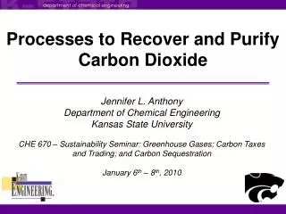
Carbon Dioxide:Generation and Capture Jennifer L. Anthony Department of Chemical Engineering Kansas State University
Carbon Dioxide Emissions 2001 In Million Metric Tons of Carbon Equivalent USA– 1579 MMT World – 6582 MMT Industrial – Non-Electricity / Non-Steam Cement Production 11.4 Ammonia Synthesis 11.0 Lime Production & Use 5.6 CO2 from natural Gas 5.0 Hydrogen Production ~3.0 Aluminum Production 1.0 Soda Ash Production & Use 0.6 Ethylene Oxide 0.2 Other Chemical Processes <1.0 TOTAL ~38 MMT from S. Barnicki (Eastman)
Carbon Dioxide Emissions 2001 In Million Metric Tons of Carbon Equivalent USA– 1579 MMT Electricity– 612 MMT from S. Barnicki (Eastman)
Representative CO2 Emission Sources from S. Barnicki (Eastman)
Conventional Fossil Fuel Steam Power Cycle Fuel: Pulv. Coal • Rankine Cycle - 25-30% efficiency • Energy in very LP steam is lost - condensed w/o energy recovery • Difficult to control pollution • Flue gas at low pressure ~1 atm Nat'l Gas Combustor / Petroleum Steam Drum 10-20% HP Steam Excess HP Turbine Air Blower HP Generator Inter- LP Turbine changer LP Generator Condensate Very LP Steam Condenser Post Flue Gas Treatment CO2 H2O N2 O2 COAL 15 % 5 % 76 % 4 % NAT’L GAS 8 % 16 % 73 % 3 % from S. Barnicki (Eastman)
CO2 Capture From Conventional Power Plant • Recovery from low pressure (~1 atm) flue gas • Low CO2 partial pressure (~1-1.5 psia) • Oxygen-containing gas (~2-5%) • Hot flue gas - 400-800 °C • May contain NOx, Hg, SO2, H2S, other sulfur species & particulates from S. Barnicki (Eastman)
Method Principle of Separation Separating Agent Physical Absorption Preferential Solubility Liquid Chemical Absorption Preferential Reactivity Reacting liquid Adsorption Difference in affinity for solid Solid adsorbent Gas Permeation Diffusion through membrane; pressure gradient membrane Conventional Methods for CO2 Capture from S. Barnicki (Eastman)
Typical CO2 Capture Process CO2 Off Gas Condenser Lean Gas Separator Drum Lean Solvent Absorber Stripping Column Trim Cooler CO2-Rich Feed Gas Interchanger Reboiler Rich Solution Condensate • Many variations possible • Physical absorbent may not require extensive heat input for regeneration • CO2 off-gas often at low pressure • May require pre-compression, depending on feed gas pressure from S. Barnicki (Eastman)
Physical Absorption • Solubility of CO2 in solvent - NO reaction • Typical absorbents: • Methanol, N-methyl-2-pyrrolidone, methyl glymes of EG oligomers, tri-n-butyl phosphate, propylene carbonate, water (not very good) • Regeneration often can be accomplished with P, limited (or no) T • Under optimal conditions generally much less energy usage than chemical absorption from S. Barnicki (Eastman)
Chemical Absorption • Chemical reaction of absorbed CO2 with solvent • Typical absorbents: • Primary, secondary, tertiary, hindered amines • MEA, DEA, MDEA, TEA, 2-AMP • Alkali metal hydroxides or carbonates • NaOH, K2CO3 , Na2CO3 • 1st, 2nd amines limited ~0.5 mol CO2/mol Amine • Tert & hindered can reach ~1.0 mol/mol • Regeneration by T & often P • Solution concentration limited by solubility, corrosion and/or reactivity with O2, contaminants from S. Barnicki (Eastman)
Chemical vs Physical Equilibrium Chemical solvent • Good at low inlet PCO2 • Can reach very low outlet PCO2 , i.e., < 10 ppm possible • Sharp rise in outlet PCO2when loading reaches rxn stoichiometry Physical solvent • Better at high inlet PCO2 • Loading proportional to PCO2 • Cannot reach very low outlet PCO2 i.e., usually 0.1-2%, but some can reach ppm levels MeOH, 0°C 20wt% DEA, 50 °C PCO2 above Liquid, atm CO2, vol/vol absorbent from S. Barnicki (Eastman)
Range of Applicability For H2S & CO2 Removal Within optimized region, costs about equivalent between methods Physical Solvents Coal Gas Syn Gases Activated Hot Potassium Carbonate, Amines, Mixed Physical/Chemical Solvents Low P Combustion Sources Auto/Diesel Nat’l Gas Power Plant Pulverized Coal Power Plant Cement Kilns Syn Gases Ammonia H2 Amines Low P Combustion Sources NaOH from S. Barnicki (Eastman)
Amine Processes • Reacts with CO2 to form carbamate complex • Many commercially available processes • Choice dictated by removal requirements, stability to stream components • Generally can be selective between for H2S / CO2 • Good for PCO2 ~ 0.1 psi or higher • Susceptible to O2 degradation, other contaminants –can be controlled • Good stage efficiencies from S. Barnicki (Eastman)
Carbonate Processes • Basic idea similar for many akali- & alkali earth hydroxides & carbonates • Choice dictated by cost & solubility in water • Non-selective between H2S / CO2 • Very best for PCO2 above ~ 10 psi, but can work at lower PCO2 • Vacuum stripping for CO2 removal to less than ~ 1000 ppm • Poor stage efficiencies – tall absorption towers • Improved with amine as catalyst from S. Barnicki (Eastman)
Components of Energy Balance in Absorptive Capture Absorber • Remove heat of absorption & reaction • Cool lean recycle solvent - sensible heat Stripper • Heat rich solvent to boiling point • Supply heat of desorption & reaction • Generate stripping/reflux vapors Possible Power Plant Capture Add-ons • Cool flue gas to absorber conditions • Compress feed gas to overcome pressure drop in Absorber • Post compression of CO2 to desired product pressure from S. Barnicki (Eastman)
Heat of Reaction: Representative Absorbents Heat of Reaction (Kcal/gmole CO2 from S. Barnicki (Eastman)
Potential Absorbents For Flue Gases • Primary Amines MEA (25 wt%) • Secondary Amines DEA (35 wt%), DIPA (40 wt%), DGA (40 wt%), • Tertiary Amines TEA (40 wt%), , MDEA (40 wt%), • Hindered Amines 2-AMP (40 wt%), 2- iPrAMP (40 wt%), 30 wt% 2-BAE / 3 wt% 2-MP • Mixed Amines 24 wt% MDEA / 6 wt% MEA • Hot Potassium Carbonate 30 wt% Unactiv. or activ. w/ DEA, AMP • Ionic Liquids from S. Barnicki (Eastman)
Conventional Power Plant Capture: Solvent Loading • Depends on reaction equilibrium • Secondary effect of solution concentration • Large effect on energy usage and equipment size from S. Barnicki (Eastman)
Energy Usage Analysis • 15% CO2 in flue gas at ~1 atm absolute pressure • 90% recovery of CO2 in flue gas • Pre-compression of flue gas to overcome pressure drop in absorber (14.7 psia to 18 psia) • Post-compression of recovered CO2 to 10 and 100 atm in two stages, w/ interstage cooling from S. Barnicki (Eastman)
Energy Usage: CO2 Capture - Compression MEA - 3.4 M BTU / Ton CO2 Absorption Step 2-AMP - 2.8 M BTU / Ton CO2 from S. Barnicki (Eastman)
Alternative solvents: Ionic Liquids X = PF6 BF4 (CF3SO2)2N Cl NO3 CH3CO2 CF3CO2 CF3SO3 Example: 1-n-butyl-3-methylimidazolium hexafluorophosphate [bmim][PF6] • Organic salts • Liquid at ambient conditions • Negligible vapor pressure • Water stable ILs (Wilkes and Zaworotko, 1992) • Solvent for a variety of industrial reactions
F To GC P Feed Gas Using [bmim][PF6] to Separate Gas Mixtures Breakthrough Curves Conventional Absorber Feed Gas: 10% CO2 in N2 [bmim][PF6] coated on glass beads Column Diameter: 1 in. Column Height: 3 in. Mass [bmim][PF6]: ~12 g T = 22 °C Feed Gas: 10% CO2 in CH4 • Proof-of-concept experiments show ILs have potential as a gas separation media • Should not contaminate gas phase (non-volatile) • Also worked in supported-liquid membrane configuration
Comparison of MEA and [bmim][PF6] Monoethanolamine • High absorbing capacity • Low hydrocarbon solubility • High volatility • Limited temperatures • High Dhrxn with CO2 • Low viscosity [bmim][PF6] • Lower absorbing capacity • Low hydrocarbon solubility • No volatility • Stable at high temperatures • Lower Dhabs with CO2 • Relatively high viscosity
Energy using MEA to Capture CO2 • Total energy: 3.4 million BTU/ton CO2 • Slightly compress the feed gas to 1.2 bar 0.15 million BTU/ton CO2 • Desorb the CO2 in the stripper 2.9 million BTU/ton CO2 • Compress the CO2 off-gas to 100 bar 2 stages at 0.18 million BTU/ton CO2 each from S. Barnicki (Eastman)
Simplified Temperature-Swing Process CO2 Off Gas Solvent Lean Gas 0.1 bar 100 % CO2 (vacuum) Stripper 100 oC Absorber 25 oC 1 bar 10 % CO2 (0.1 bar CO2) Feed Gas CO2-rich Solvent Solvent
Energy Balance Q: energy needed for desorption Dhabs: enthalpy of absorption for [bmim][PF6] or the enthalpy of reaction for MEA m: mass of solvent to absorb 1 kg CO2 Cp: heat capacity of the solvent DT: temperature difference between the absorption and desorption step
Parameters Dhrxn(30 wt% MEA in H2O) = - 85.4 kJ / mol CO2 Dhabs([bmim][PF6]) = -16.1 kJ / mol CO2 m(30 wt% MEA in H2O) = 17 kg / kg CO2 m([bmim][PF6]) = 5914 kg / kg CO2 Cp(30 wt% MEA in H2O) = 4.18 kJ / kg K Cp([bmim][PF6]) = 1.0 kJ / kg K (low) = 2.5 kJ / kg K (high) Actual Cp for [bmim][PF6]: At 25 oC: 1.40 kJ/kg*K At 100 oC: 1.48 kJ/kg*K
Energy for CO2 Absorption and Recovery Temperature-swing (25 oC to 100 oC) CO2 partial pressure = 0.1 bar
Energy for CO2 Absorption and Recovery Temperature-swing (25 oC to 100 oC) CO2 partial pressure = 0.1 bar
Energy for CO2 Absorption and Recovery Temperature-swing (25 oC to 100 oC) CO2 partial pressure = 0.1 bar Chemical Absorbent Determined by Stoichiometry 0.5 mol CO2/mol MEA
Energy for CO2 Absorption and Recovery Temperature-swing (25 oC to 100 oC) CO2 partial pressure = 0.1 bar Chemical Absorbent Limited by Stoichiometry 0.5 mol CO2/mol MEA Physical Absorbent PCO2 dependent
Feed Pressure Effects Temperature-swing calculations but with varying CO2 partial pressures
Pressure Swing Absorber Lean Ionic Liquid Lean Gas Absorber CO2-Rich Feed Gas CO2 Saturated Ionic Liquid (P = 1 atm) (P = 1 atm) Compressor Compressor CO2 Off Gas
Using MEA to Capture CO2 • Total energy: 3.4 million BTU/ton CO2 • Slightly compress the feed gas to 1.2 bar 0.15 million BTU/ton CO2 • Desorb the CO2 in the stripper 2.9 million BTU/ton CO2 • Compress the CO2 off-gas to 100 bar 2 stages at 0.18 million BTU/ton CO2 each from S. Barnicki (Eastman)
Ideal IL Henry’s Constant to Compete with MEA [bmim][PF6] @ 25 oC: H ~ 53 bar Temperature-swing (25 oC to 100 oC)
Ideal IL Henry’s Constant to Compete with MEA [bmim][PF6] @ 25 oC: H ~ 53 bar Temperature-swing (25 oC to 100 oC) [bmim][Tf2N] @ 25 oC: H ~ 30 bar Jim Davis TSIL with amine on cation: H ~ 3 bar
Conclusions • [bmim][PF6] not capable of replacing MEA • Need higher CO2 carrying capacity • Combination temperature-swing and pressure-swing for CO2 capture and solvent regeneration could decrease energy usage • Necessary improvement seems within reason