Download
1 / 9
90 likes | 172 Views
Learn how to navigate the complexities of read-modify-write instructions for effective port control in microcontrollers. Understand the importance of proper sequencing and precautions when setting I/O pins.

E N D
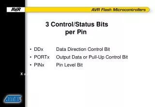
3 Control/Status Bits per Pin • DDx Data Direction Control Bit • PORTx Output Data or Pull-Up Control Bit • PINx Pin Level Bit X = A, B, C, ...
Default Configuration DDx 0 Pull-Up PORTx 0 PINx Physical Pin ? ? Direction: INPUT Pull-Up: OFF
1 Switch On Pull-Up DDx 0 Pull-Up PORTx 1 1 PINx Physical Pin ? ? Direction: INPUT Pull-Up: ON
1 1 1 Port is Output DDx 1 Pull-Up PORTx 1 1 PINx Physical Pin 1 1 Direction: OUTPUT Pull-Up: OFF
Why Three Addresses? Why not let WRITE PORTx write the LATCH and READ PORTx read the PINS? (just like Microchip, Hitachi, Motorola...) A Two-address Port means NO REAL Read-Modify-Write
The Two-Address Problem Example: • I/O Type: PORTx Reads the Pin and Writes the Latch • Configuration: Some PORTx Pins are Outputs, Others are Inputs, Inputs Have Pull-Ups on • Software Task: Set One of the Output Pins PROBLEM!
The Two-Address Problem (Continued) • Setting an I/O Pin is Done Like This: • Read PORT x (Read) • OR With All Zeros Except Bit to be Set (Modify) • Write PORT x (Write) • If the Signal on an Input Pin is Low When PORT x is Read... Write Back WILL TURN OFF THE PULL-UP.
From the PIC16C64 Datasheet: “Reading the PORT register, reads the values of the PORT pins. Writing to the PORT register writes the value to the PORTB latch. When using read modify write instructions (ex. BCF, BSF, etc.) on a PORT, the value of the PORT pins is read, the desired operation is done to this value, and the value is then written to the PORT latch” .” … “…care must be exercised if a write followed by a read operation is carried out on the same I/O port. The sequence of instructions should be such to allow the pin voltage to stabilize (load dependent) before the next instruction … otherwise, the previous state of that pin may be read into the CPU rather than the new state … it is better to separate these instructions with a NOP or another instruction not accessing this I/O port.”
From Hitachi's H8/300 Programming Manual: “BSET, BCLR, … are read-modify-write instructions. They read a byte of data, modify one bit in the byte, then write the byte back. Care is required when these instructions are applied to registers with write-only bits and to the I/O port registers.” … “Programming Solution: The switching of the pull-ups can be avoided by storing the same data both in the port data register and in a work area in RAM”