Download
1 / 20
200 likes | 325 Views
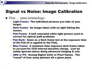
KFPA Noise Calibration Module and Coupler. Eric W. Bryerton NRAO CDL (Charlottesville). EVLA 18-26.5 GHz Receiver. Thermal Gap. 15 ºKelvin Cold Stage. Phase-Shifter. Cold Straps. RCP LNA. LCP LNA. Cryo Isolator. Cryo Isolator. Cal Coupler. Cal Coupler. Ortho-Mode Transducer.

E N D
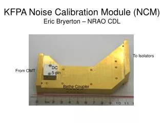
KFPA Noise Calibration Module and Coupler Eric W. Bryerton NRAO CDL (Charlottesville)
EVLA 18-26.5 GHz Receiver Thermal Gap 15ºKelvin Cold Stage Phase-Shifter Cold Straps RCP LNA LCP LNA Cryo Isolator Cryo Isolator Cal Coupler Cal Coupler Ortho-Mode Transducer Stainless Steel Coax
Options for Cold Noise Calibration Source • MMIC LNA • Single HEMT • GaAs Schottky Diode • Tested 3 different K-Band MMIC LNAs • Hittite HMC517, HMC519, and UMS CHA2092b • Output Noise should be (Gain * Noise Temperature) • Can we get enough noise with low power dissipation?
Dewar Bottom Plate Dewar Top Plate Phase Shifter Noise Coupler OMT Feed LNA Isolator KFPA Cold Pixel
KFPA Noise Cal Module Specifications • RF In/Out: WR42, UG595/U Flange • RF Channel Isolation: 40 dB • Equivalent Injected Noise: 1.5-6.0 K • Injected Noise Flatness: TBD (xxdB/yyMHz) • Dissipated Power: 15 mW maximum to 15K stage • Response Time: 100 us maximum rise/fall • Stability: +/- 3% over 4 hours (TBC), TBD over 1 year • NOT CAL: TTL Low -> Injected Noise ON
Noise Cal Test Block MMIC LNA
Noise Cal Test Block Measurements Measure Pon/Poff ratio, then:
Noise Cal Test Block Measurements LNA 20dB Atten Noise Cal Test Block
Noise Cal Test Block Measurements 11mA 10mA 8mA VDS=0.85V -> PDC=6.8mW for bottom trace
Added Noise Versus Cal Coupling • Not including ohmic losses • 25dB coupler adds about 0.05K more noise than 30dB coupler
Noise Cal Test Block Measurements 22.25 GHz, Vds=0.85V, Vgs=-0.54V, Ids=10mA
+3% -3% Noise Cal Test Block Measurements 22.25 GHz, Vds=0.85V, Vgs=-0.54V, Ids=10mA 9:40am
Noise Cal Test Block Measurements 22.25 GHz, Vds=0.85V, Vgs=-0.54V, Ids=10mA +3% -3% 3:39pm
Noise Cal Test Block Measurements 22.25 GHz, Vds=0.85V, Vgs=-0.54V, Ids=10mA +3% -3% 7:20pm
Noise Cal Test Block Measurements • To keep bias fluctuations from changing Tcal more than 0.2%: • VDS stable to within +/- 1 mV • VDS stable to within +/- 10 uV (or, IDS stable to within +/- 5 uA)
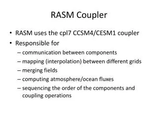
P4 P1 P6 P3 P2 P5 6-Port Bethe Coupler CST Simulations P1: noise source P2: load for uncoupled noise cal power P4->P3, P6->P5: main signal path (OMT->isolator)
6-Port Bethe Coupler CST Simulations • Coupling = -30.5 +/- 0.5 dB (S31, S51)
6-Port Bethe Coupler CST Simulations • Input Match (noise source and signal path) < -40 dB (S11, S44) • Channel-to-Channel Isolation > 60 dB (S54) • Directivity >20 dB (S31/S41)
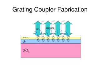
Integrated Noise Cal/Coupler Block for Single Pixel Prototype • Gold-plated aluminum block • Coupling holes are 0.100” diameter