Download
1 / 36
880 likes | 1.39k Views
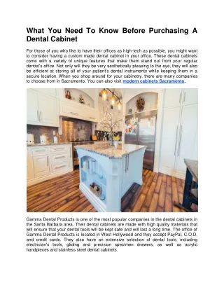
Cabinetry. Cabinet. The cabinet assembly is made up of a backbox and a door assembly. Four sizes of fire alarm cabinets are available: A , B, C and D.

E N D
Cabinet The cabinet assembly is made up of a backbox and a door assembly. Four sizes of fire alarm cabinets are available: A, B, C and D. The letters correspond to the number of rows available inside the cabinet. (There is a dedicated area at the bottom of the cabinet for the optional power supply and batteries.) Many peripheral components of a ONYX fire system have their own cabinet enclosures.
A-4 Series Cabinets Number of Rows A=1 B=2 C=3 D=4 PS & Batteries R = RED Nothing here meansthe color will be black. 4 Series DR – C4BR DR = DooR SBB = Surface Back Box B = Blank Door (not Black) Nothing here means glass front door
CAB-4 Series backbox One available row A-size backbox DR-A4 PS & Batteries PS & Batteries PS & Batteries PS & Batteries Two available rows B-size backbox DR-B4 Three available rows C-size backbox DR-C4 Four available rows D-size backbox DR-D4
CHASSIS1 CHASSIS 1 CHASSIS 1 CHASSIS 1 CHASSIS 2 CHASSIS 2 CHASSIS 2 CHASSIS 3 CHASSIS 3 SBB-A4 CHASSIS 4 SBB-B4 • Chose a backbox • Most display-less nodes will be A or B size • Add “R” suffix for RED SBB-C4 SBB-D4
CHASSIS 1 CHASSIS 1 CHASSIS 1 CHASSIS 1 CHASSIS 2 CHASSIS 2 CHASSIS 2 CHASSIS 3 CHASSIS 3 SBB-A4 DR-A4B CHASSIS 4 SBB-B4 DR-B4B SBB-C4 DR-C4B SBB-D4 DR-D4B • Door part numbers correlate to the backbox size • Doors are solid metal (blank) • Add “R” suffix for RED
Chassis and Dress Plates • CHS-4 Chassis, mounts up to four loop and/or network cards. • CHS-4L Chassis, low profile, for mounting loop and network cards, or LDM. • DP-1B Dress panel, blank, covers an entire 4-position row in the cabinet. • BMP-1 Blank Dress Plate, single position, covers unused modules slots in a ADP-4. D-Size Backbox
There are four basic types of ONYX systems: • NFS2-3030 without a display (CPU2-3030ND) and a blank door (display-less node) • NFS2-3030 (CPUS-3030D) with a display, but no Digital Voice • NFS2-3030 with a display, and with Digital Voice and a Paging Microphone • NFS2-3030 with a display, and with Digital Voice, a Paging Microphone and a Fire Fighter’s Telephone
Steps: • Backbox • Door • CPU Chassis • CPU • Power Supply • Network interface card • SLC interface card(s)
CPU: • CPU2-3030ND • NFS2-3030 CPU without a display • Power Supply: • AMPS-24 • Primary Power Supply • Add “E” suffix for 220 VAC • Network Interface Card • NCM-W Wire • NCM-F Multi-Mode Fiber
SLC Interface: • LCM-320CLIP/FlashScanTMControl Module • LEM-320 Expander for LCM-320 • Up to five pair may be installed per NFS2-3030 CPU • Total 10 SLCs
CHS-M3 • Mounts the CPU • Uses Positions 1 and 2 • Mounts SLC interface cards • LCM-320 / LEM-320 • Positions 3,4 • Stacked (total 4) • Mounts Network interface cards • NCM-W / NCM-F • Positions 3,4 • Stacked (total 4) 1 2 3 4 Option Modules NFS2-3030-CPU
CA-2 Chassis Specifically for this use NFS2-3030or NCA-2 DVC-EM DVC-KD Microphone Order TELH-1 Telephone separately For networks, NCM-W/F can mount behind the DVC.
Microphone, Fire Fighter Telephone A microphone and Fire Fighter’s Telephone are housed in a cage assembly that mounts to the right of the CPU/ DVC. These devices connect to the Digital Voice Controller. CA-1 Connects to DVC CPU D-Size Backbox CMIC-1 An alternate assembly provides a housing for a single microphone alone.
Audio Configurations In a Digital Voice Command system, either a NFS2-3030 CPU or a NCA-2 may be housed above the voice controller. Loop Control Modules may be installed underneath the CPU or in a dedicated row within the cabinet. The Power Supply and batteries are mounted in the standard position inside the cabinet or battery enclosure. D-Size Backbox An LCM-320/LEM assembly mounted under CPU position
Chassis The CHS-4 Chassis is used to mount a variety of devices. It covers one row in the cabinet and provides four positions for loop and/or network cards. D-Size Backbox there are many mounting combinations for the CHS-4, some four layers deep! • Mounting Options: • SBB Backbox Four LCM-LEM assemblies mounted in the CHS-4 Chassis
Chassis, Dress Panels & Plates The CHS-4 is a versatile chassis that can be used to mount a variety of modules – loop cards, network cards, relay cards, etc. The ADP-4B Dress Panel provides for the mounting of annunciators over the top of other modules mounted insider the cabinet.
Loop Control Modules in aDigital Voice Command System LCM-320/ with LEM-320 Expander installed under CPU position Four LCM-320/LEM-320 assemblies in a chassis.
SBB-B4 • CHS-M3 • NFS2-3030 • LCM-320 • NCM-W • AMPS-24 • Batteries • DR-B4B
Same BOM as non-display, except: NFS2-3030 DP-DISP mounting plate (2) BMP-1 blank plates DR-B4 Four ACM-24AT Annunciators used in this example with ADP-4B dress plate
Same BOM as Type 2, except add: • CA-1: Chassis • DVC-EM: DVC CPU • DVC-KD: Keypad • CMIC-1: Microphone • DPA-1: dress plate • Note: • “C” Cabinet used in this example with ACM-24AT Annunciators
CA-2 • BOM changes from Type 3: • CA-2: Chassis (CA-1) • DPA-2B: dress plate (DPA-1) • TELH-1: Telephone (CMIC-1) • Note: • “C” Cabinet used in this example with ACM-24AT Annunciators
Digital Voice Command The Digital Voice Command is Honeywell’s voice evacuation solution. This system is most often comprised of the following components: • CPU or Network Control Annunciator • Loop Control Modules • Digital Voice Controller • Microphone • Telephone Handset • Mic/Phone wells • Special chassis • Digital Amplifiers • Power Supply • Batteries • B, C or D-size Cabinet • Special Cabinet Doors • Network Control Modules
Digital Voice Controller • The center of the Digital Voice Command system is the controller assembly. The assembly (shown below) has a keypad, motherboard and an optional ANALOG audio output board which generates the low-level analog audio signals for existing or new analog systems. • Eight channels of digital audio • 5 FFT channels • 32 addressable Digital Amplifiers • Style 4 or 7 • 1000 Message Capability. • 32 Minute Audio Storage Capacity. D-Size Backbox DVC-KD Interface
Analog Output Option The DVC-AO Analog Output board provides the DVC with the capability to drive up to four analog amplifiers for four Channel audio. The unit mounts on top of the DVC main board, underneath the KD interface. D-Size Backbox DVC-AO Option Board
Digital Audio Amplifiers • The DVC system can employ two versions of audio amplifiers – the -DAA-5025 (50 Watt, 25 Volt) and the -DAA-5070 (50 Watt, 70 Volt). • These amplifiers are self-contained assemblies that consume one row in the cabinet. The assemblies contain a chassis, power supply, battery charger, battery rack, and on-board speaker circuits (4 Class B or two Class A). • 32 Amplifiers max • New for System 4.0 are the DAA2, DAX and BDA(Backup Digital Amplifier) amplifiers. • The DS-FM module allows for wire to fiber transitions on the new System 4.0 amplifiers. D-Size Backbox Digital Audio Amplifier Assembly
Distributed Amplification • Distributing the amplifiers throughout the protected premises minimizes high-level signal loss and increase the survivability of the overall system. • Backup amplifiers are on a ONE-to-MANY basis. Note: when using a DAA2 with BDA as a backup that configuration is One to One. • Distributing the amplifiers throughout the protected premises minimizes high-level signal loss and increase the survivability of the overall system. • Amplifiers can be installed in successive rows within the cabinet provided background music is not employed. DAA amplifier in a C-Size enclosure An amplifier mounted in a separate cabinet.
Chassis, Dress Panels & Plates Often one of the most overlooked components of a fire alarm system is the mounting hardware and dress plates necessary to complete the system. • Chassis are used to mount components inside the cabinet. • Dress plates cover module positions or rows within the cabinet. • Trim Rings cover gaps in the wall around the control panel or remotely-mounted devices, such as amplifiers. Mounting well for microphone and telephone. Half-Chassis for NFS2-3030 CPU. Half-Chassis for Digital Voice Controller. Back plate for affixing CA-2 assembly to the backbox.
Chassis, Dress Panels & Plates Dress panels for use with the Digital Voice Evacuation system DPA-1 Dress Plate Audio, 1 row DPA-1A4 - supports 4 Annunciators ADP-4B Annunciator Dress Plate
Chassis, Dress Panels & Plates Most hardware used in an ONYX system has multiple applications. Network Application Stand Alone Application NFS2-3030 CPU NCA-2 DVC-EM DVC-EM Loop Modules Loop & Network Modules Dress Panel covers power supply and batteries
Digital Voice Command System Doors ADDR-B4 B-Size Cabinet Door ADDR-C4 C-Size Cabinet Door ADDR-D4 D-Size Cabinet Door
Chassis The CHS-4L is a low profile chassis used to mount a variety of devices. It covers one row in the cabinet and provides four positions for loop and/or network cards. D-Size Backbox Two LCM-LEM assemblies mounted in the CHS-4L Chassis • Mounting Options: • SBB Backbox
Dress Plates The ADP-4B is a dress plate for the face-mounting of various annunciators. The plate covers one row in a SBB series cabinet and features a swing hinge for easy access to mounted components. ADP-4B with NCA2 Retro Kit and 2 ACS Annunciators ADP-4B with 4 ACS Annunciators the BMP-1 is a blank plate used to cover unused module positions in the ADP-4B • Mounting Options: • SBB Backbox
Quiz: Audio System Components Match the Digital Voice Command system component with a typical mounting location within the cabinet. Batteries ● Digital Audio Amplifier ● Microphone/Telephone Cage ● Central Processing Unit ● Digital Voice Command Module ● Main Power Supply ● Loop Modules ●