Download
1 / 77
800 likes | 933 Views
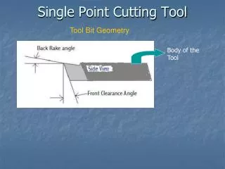
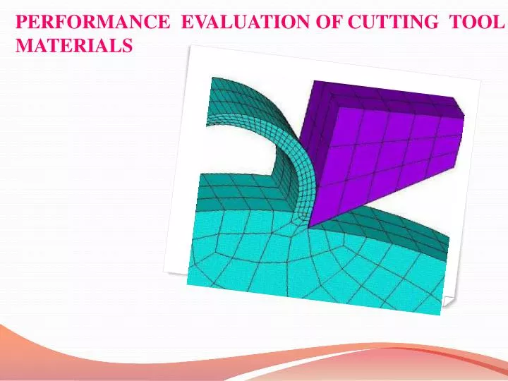
PERFORMANCE EVALUATION OF CUTTING TOOL MATERIALS. UNDERSTANDING CHIP FORMATION. Tool geometry Solid mechanics Fracture mechanics Yielding mechanism Dislocations etc. TOOL GEOMETRY. FRACTURE MECHANICS.

E N D
UNDERSTANDING CHIP FORMATION • Tool geometry • Solid mechanics • Fracture mechanics • Yielding mechanism • Dislocations etc
FRACTURE MECHANICS Fracture mechanics is the field of mechanics concerned with the study of the formation of cracks in materials It uses the method of analytical solid mechanics to calculate the driving force on a crack and those of experimental solid mechanics to characterize the materials resistance to fracture
FRACTURE MECHANICS ELASTIC BEHAVIOUR • When a material is being loaded in uni-axial tension, compression, or simple shear it will behave elastically until a critical value of normal stress or shear stress is reached and then it will behave plastically. • If the applied loads are relatively low, the crystal responds by simply stretching or compressing the distance between the atoms. The basic lattice unit does not change, and all of the atoms remain in their original position relative to one another. • Elastic deformation stretches atomic bonds in the material away from their equilibrium radius of separation of a bond, without applying enough energy to break the inter-atomic bonds.
FRACTURE MECHANICS PLASTIC DEFORMATION • As the magnitude of applied load is increased, the distortion increases to a point where the atoms must either (1) break bonds to produce a fracture, or (2)slide over one another to produce a permanent shift of atoms position. • Plastic deformation is the shearing of atomic planes over one another to produce a net displacement. • Plastic deformation tends to occur along planes having the highest atomic density and greatest separation. • Thus plastic deformation occurs by the preferential sliding of maximum-density planes. • The specific combination of plane and direction is called a slip system, and the shear deformation is known as slip
THEORY OF DISLOCATION • Dislocations are defined as line defects in a material's crystal structure. They are surrounded by relatively strained (and weaker) bonds. • Dislocations are generated and move when a stress is applied. The motion of dislocations allows slip – plastic deformation to occur. • Edge dislocations allow slip to occur and slip provides ductility in metals.
WORK HARDENING • Work hardening, also known as strain hardening, is the strengthening of a metal by plastic deformation. This strengthening occurs because of dislocation movements within the crystal structure of the material. • Increase in the number of dislocations is a quantification of work hardening. Plastic deformation occurs as a consequence of work being done on a material; energy is added to the material. • However, ductility of a work-hardened material is decreased. Ductility is the extent to which a material can undergo plastic deformation, that is, it is how far a material can be plastically deformed before fracture.
The dislocation density increases due to the formation of new dislocations and dislocation multiplication. The consequent increasing overlap between the strain fields of adjacent dislocations gradually increases the resistance to further dislocation motion. This causes a hardening of the metal as deformation progresses. This effect is known as strain hardening(also “work hardening”). • If dislocation motion and plastic deformation have been hindered enough by dislocation accumulation, and stretching of electronic bonds and elastic deformation have reached their limit, a third mode of deformation occurs: fracture
FRACTURE • There are in general two types of fracture-ductile fracture and brittle fracture • Ductile fracture occurs after appreciable plastic strain. • Brittle fracture occurs at a strain that is below the yield stress.
GRIFFITH’S THEORY • Griffith suggested that the low fracture strength observed in experiments, as well as the size-dependence of strength, was due to the presence of microscopic flaws in the bulk material. • To verify the flaw hypothesis, Griffith introduced an artificial flaw in his experimental specimens. The artificial flaw was in the form of a surface crack which was much larger than other flaws in a specimen.
The experiments showed that the product of the square root of the flaw length (a) and the stress at fracture (σf) was nearly constant, which is expressed by the equation: Griffith developed a thermodynamic approach to explain the relation that he observed. The growth of a crack requires the creation of two new surfaces and hence an increase in the surface energy Griffith found an expression for the constant C in terms of the surface energy of the crack by solving the elasticity problem of a finite crack in an elastic plate. Briefly, the approach was:
Compute the potential energy stored in a perfect specimen under an uniaxial tensile load. • Fix the boundary so that the applied load does no work and then introduce a crack into the specimen. The crack relaxes the stress and hence reduces the elastic energy near the crack faces. On the other hand, the crack increases the total surface energy of the specimen. • Compute the change in the free energy (surface energy − elastic energy) as a function of the crack length. Failure occurs when the free energy attains a peak value at a critical crack length, beyond which the free energy decreases by increasing the crack length, i.e. by causing fracture. Using this procedure, Griffith found that
Where E is the Young's modulus of the material and γ is the surface energy density of the material. Assuming E = 62 GPa and γ = 1 J/m2 gives excellent agreement of Griffith's predicted fracture stress with experimental results for glass.
OBSERVATIONS Cutting process generates heat. Thickness of the chip is greater than the thickness of the layer from which it came. Hardness of the chip is greater than the hardness of the parent material.
These observations indicate that the process of chip formation is one of deformation or plastic flow of the material. Plastic flow takes place by means of a phenomenon called slip along the slip plane. As the tool touches the work the work gets deformed initially the deformation is elastic in nature. As the tool gets forward applying more force the elastic limit is overcome, the material starts flowing plastically.
During the plastic deformation, shearing of the atoms take place this in turn leads to dislocation(edge and screw) to occur in the material. This shearing action takes place along the slip plane or the shear plane. Due to the dislocation the atoms are separated and reformed and dislocation increases the ductility of the material. As a result the material flows plastically up to a point after which ductility decreases and the material becomes more harder the process is called as work hardening. Beyond this point the material becomes brittle and harder and with the further increase in the load leads to the fracture in the material
During the dislocation taking place the atoms are subjected to severe tension and compressive force as a result tensile and compressive strain field is created which eventually increases the hardness of the material . As the metal approaches the shear plane , it does not deform until the shear plane is reached. It then undergoes substantial amount of shear as it crosses a thin primary shear zone. There is no further plastic flow as the chip proceeds up the face of the tool. The small amount of secondary shear along the tool face is generated as the chip flows over the tool in turn generating the friction.
The back of the chip is rough due to the strain being inhomogeneous. This is due to the presence of points of weakness or stress concentration present in the metal being cut. The shear plane passing through a point of stress concentration will deform at a lower value of stress than one that does not include a point of stress concentration. Thus some material in the chips strains more than the other metal resulting in wavy surface on the back of the chip.
THE CARD MODEL This model assumes the material cut as a deck of cards. Exaggerates the in homogeneity of strain. Assumes shear to occur on a perfectly plane surface. Ignores any built up edge that may be present. Involves an arbitrarily assumed shear angle. This model says that; All atomic planes are not active shear planes, but only those associated with a structural defect (second phase particle, missing atom, an impurity, a grain boundary, etc). This results in in homogenous strain and a series of sharp points on both surfaces of the chip. The points on the free surface remain and serve as an indication of the degree of in homogeneity pertaining.
Those on the tool face side are removed by burnishing. If the structural defects are widely spaced, the free surface of the chip will have a saw-toothed appearance. For less intense and less widely spaced defects, the free surface of the chip will be relatively smooth. The teeth will not extend continuously across the chip but will be localized and staggered.
CHIP FORMATION ANALYSIS The friction between the tool and the work material plays an important role in metal cutting, this friction can be reduced by Improved tool finish and sharpness of the cutting edge. Use of low-friction work or tool materials. Decreased cutting speed (v) Increased rake angle. Use of a cutting fluid. .
When the friction reduces there is a corresponding increase in the shear angle accompanying the decrease in the thickness of the chip. The plastic strain in the chip decreases with the increases in the shear angle. The length of the shear plane significantly decreases with the increase in the shear angle. Therefore the force along the shear plane decreases with the decrease in the shear area. The temperature of a cutting tool may reach a high value particularly when a heavy cut is taken at a high speed.
MECHANICS IN METAL CUTTING The force acting on a cutting tool during the process of metal cutting are the fundamental importance in the design of cutting tools. The determination of cutting forces necessary for deformation the work material at the shear zone is essential for several important requirements: • To estimate the power requirements of a machine tool. • To estimate the straining actions that must be resisted by the • machine tool components, bearings, jigs and fixtures. • To evaluate the role of various parameters in cutting forces. • To evaluate the performance of any new work material, tool • material, environment, techniques etc,with respect to machinability • (cutting forces).
When the chip is isolated as a free body, we need to consider only two forces-the force between the tool face and the chip (R) and the force between the work piece and the chip along the shear plane (R’). For equilibrium these must be equal. R=R’ The forces R and R’ are conveniently resolved into three sets of components as indicated in figure. • along and perpendicular to the shear plane, Fs and Fn. • along and perpendicular to the tool face, F and N. • in the horizontal and perpendicular to the tool face, Fc and Ft.
MERCHANT CIRCLE ANALYSIS If the forces R and R’ are plotted at the tool point instead of at their actual points of application along the shear plane and tool face, we obtain a convenient and compact diagram. This type of plot was suggested by merchant (1945) and the corresponding diagram is called as the merchant circle diagram which is as shown
Energy dissipated Heat Temperature rise Tool Shearing Problem Machine Tool Machining process Work part
The main sources of heat in metal cutting are shown in the Figure. These three distinct heat sources are: • the shear zone (q1), where the main plastic deformation takes place • the chip-tool interface zone (q2), where secondary plastic deformation due to friction between the heated chip and the tool takes place • the work tool interface (q3), at flanks where frictional rubbing occurs.
The power consumed in metal cutting is largely converted into heat near the cutting edge of the tool, and many of the economic and technical problems of machining are caused directly or indirectly by this heating action. The cost of machining is very strongly dependent on the rate of metal removal, and costs may be reduced by increasing the cutting speed and the feed rate. Machining is inherently characterized by generation of heat and high cutting temperature. At such elevated temperature the cutting tool if not enough hot hard may lose their form stability quickly or wear out rapidly resulting in increased cutting forces, dimensional inaccuracy of the product and shorter tool life.
The magnitude of this cutting temperature increases, though in different degree, with the increase of cutting velocity, feed and depth of cut, as a result, high production machining is constrained by rise in temperature. This problem increases further with the increase in strength and hardness of the work material. Knowledge of the cutting temperature rise in cutting is important, because increases in temperature:
Following are the observations depicted from the above figure • Maximum temperature is about halfway up the face of the tool • Steep temperature gradient across the thickness of the chip. • Some chips may become red hot, causing safety hazards to the operator and thus necessitating the use of safety guards.
Work part Tool • Dimensional change • Thermal damage • Loss of strength • Decrease hardness • Increased wear rate • Thermal damage Machine Tool • Distortion
ADVERSE EFFECTS DUE TO TEMPERATURE RISE • Adversely affect the strength, hardness and wear resistance of the cutting tool • Cause dimensional changes in the part being machined, making control of dimensional accuracy difficult • Can induce thermal damage to the machined surface, adversely affecting itsproperties and service life.
The heat balance in chip formation can be written as: Total amount of heat generated = (Amount of heat away in chips ) + (Amount of heat remaining in the cutting tool )+ (Amount of heat passing into the work piece )+ (Amount of heat radiated into the surrounding).
when a material is deformed elastically, the energy required for the operation is stored in the material as strain energy, and no heat is generated. However, when a material is deformed plastically, most of the energy used is converted into heat. In metal cutting the material is subjected to extremely high strains, and the elastic deformation forms a very small proportion of the total deformation; therefore it may be assumed that all the energy is converted into heat.
Various studies have been made of temperatures in cutting, based on heat transfer and dimensional analysis, using experimental data. A simple and approximate expression for the mean temperature fororthogonal cutting is K = thermal diffusivity (ratio of thermal conductivity to volumetric specific heat) of the Work piece material (m2/sec). pC = volumetric specific heat of the work piece (J/mm2-C) t = depth of cut (mm) V = cutting velocity (m/sec) c U = specific energy in the operation (N-m/mm3) T = mean temperature rise at the tool-chip interface (oC).
DEFINITION The change of shape of the tool from its original shape, during cutting, resulting from the gradual loss of tool material . • OBJECTIVES • Study the general characteristics of tool wear • Understand the causes of tool wear and their consequences • Set up the tool failure criteria and understand the meaning of tool-life
Cutting tools are subjected to an extremely severe rubbing process. They are in metal-to-metal contact between the chip and work piece, under conditions of very high stress at high temperature. The situation is further aggravated (worsened) due to the existence of extreme stress and temperature gradients near the surface of the tool. • During machining, cutting tools remove material from the component to achieve the required shape, dimension and surface roughness (finish). However, wear occurs during the cutting action, and it will ultimately result in the failure of the cutting tool. When the tool wear reaches a certain extent, the tool or active edge has to be replaced to guarantee the desired cutting action.
TOOL WEAR PHENOMENA The high contact stress between the tool rake-face and the chip causes severe friction at the rake face, as well, there is friction between the flank and the machined surface. The result is a variety of wear patterns and scars which can be observed at the rake face and the flank face CRATER WEAR FLANK WEAR NOTCH WEAR CHIPPING ULTIMATE FRACTURE.
RAKE FACE WEAR Crater wear: The chip flows across the rake face, resulting in severe friction between the chip and rake face, and leaves a scar on the rake face which usually parallels to the major cutting edge. The crater wear can increase the working rake angle and reduce the cutting force, but it will also weaken the strength of the cutting edge. The parameters used to measure the crater wear can be seen in the diagram. The crater depth KT is the most commonly used parameter in evaluating the rake face wear.