Download
1 / 47
470 likes | 577 Views
How everything started…. Direct link between brain and computer. 1985: Peter Fromherz, Max Planck Institute of Biochemistry. How to design a neuron-silicon junction?. Content. Neuronal signaling Neuron architecture Membrane potential Action potential Neuro-Transistors

E N D
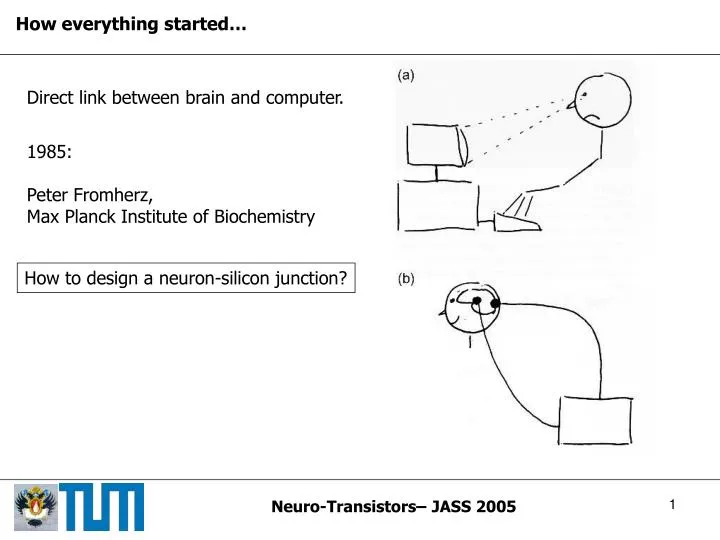
How everything started… Direct link between brain and computer. 1985: Peter Fromherz, Max Planck Institute of Biochemistry How to design a neuron-silicon junction?
Content • Neuronal signaling • Neuron architecture • Membrane potential • Action potential • Neuro-Transistors • Point-Contact Model • Transistor recording • Capacitive stimulation • Two neurons and a chip
Architecture of a neuron Basic functional units: Input component Dendrites Trigger component Cell body (soma) Long-range conducting component Axon Output component Presynaptic terminals
Signaling Neurons communicate by electrical signaling. Action potential: Brief, invariant and large electrical pulse All-or-none signal Frequency-coded
The cell membrane Double layer of hydrophobic lipid molecules Membrane proteins: • voltage-gated ion channels • ligand-gated (chemically- controlled) ion channels • energy consuming ion pumps Control transport of ions throughthe cell membrane.
Membrane Potential Separation of charges across membrane Membrane potential: Potential determined by: Ionic conductances of the cell membraneDistribution of ions across the membrane(mainly potassium and sodium ) Reduction in charge separation: Depolarization Increase in charge separation: Hyperpolarization
Membrane Potential -ions concentrated inside the cell. Charge separationacross the membrane. Chemical force drivingthem outside downconcentration gradient. Potential difference acrossthe membrane driving -ions back into the cell.
Membrane Potential Equilibrium: Chemical force = Electrical force Equilibrium potential: Nernst Equation Giant squid axon: Passive process, consumes no energy. Energy is needed to set up initial concentration gradients. Ion pumps: Proteins in cell membrane. Ion transport through hydrolysis of ATP to ADP.
Equilibrium with several ion species: Ion flux = (electrical force + chemical force) x membrane conductance Influence of each ion species by concentration gradient and permeability of membrane Membrane potential described by Goldman-Hodgkin-Katz equation: GHK Equation usually around -60mV.
Generation of an action potential Membrane potential and ionic conductancescomputed from the Hodgkin-Huxley model.
Recording electrical signals from neurons: Small glass micropipettes (d < 1µm) filled with concentrated salt solutionare inserted into the cell. Connection via an amplifier to an oscilloscope.
Voltage-clamp technique: Difficult to examine ion conductances and because of their strong voltage dependence. Holding (clamping) the potential in the cell at a certain value. Opening of voltage-gated ion channels does not affect membrane potential.
Patch-Clamp Technique Allows measurement of currentsthrough single ion channels. Suction Seal between electrode and membrane. Reduction of electronic noise.
Signal Propagation along the Axon Axon can be described as one-dimensional cable. Cell membrane: insulating coat Intracellular fluid: conductive core Conduction velocity depends on: Diameter of axon (Giant squid axon d=1mm) Insulation of axonal membrane
Myelination Conduction velocity: Myelin: electrically insulating layer around axons. Unmyelinated: v = 5 to 10 Myelinated: up to v = 150 Nodes of Ranvier
Synapses Chemical signal transmission across the synaptic cleft. Action potential Neurotransmitter release Neural plasticity:Regulation of synaptic strength. Learning and memory
Where to go? Today: Trying to understand fundamental principles of neuron-silicon junctions. Physical rationalization of junction to optimize neuron-silicon interfacing Hybrid systems with neuronal networksand microelectronic devices. ……….. Today Science-Fiction
Principles of coupling (a) Electrical field across the membrane polarizes the silicon dioxide on the chip. (b) Electrical field across the silicon dioxide polarizes the membrane affecting voltage- gated ion-channels. Unfortunately: Proteins from cell membrane keepmembrane at certain distance fromthe chip. (c) Neuronal activity leads to ionic and displacement currents through the membrane. Current spreads along the cleft. Transductive Extracellular Potential (TEP) (d) Voltage transient applied to silicon causes displacement current through oxide. Transductive Extracellular Potential (TEP)
Point-Contact Model Transductive extracellular potential mediates coupling of neuron and silicon. TEP is determined by current balance in junction. Point-Contact Model Capacitance of the Membrane: , Ionic conductances: , Capacitance of the chip: , Conductance of the cleft: ,
Point-Contact Model Kirchhoff‘s law:
Point-Contact Model :Area of the free membrane. :Area of the attached membrane. Current balance in the cell:
Point-Contact Model Remarks: ionic conductances depend on voltage difference across the membrane (Hodgkin-Huxley-Model). point-contact model assumes that all currents flow through one point in the membrane. Parameters , , represent average values. point-contact model is a simplification of an area-contact modelwhere depends on the position in the junction. Efficient recording and stimulation: small distance high specific resistance large radiushigh ionic conductanceshigh capacitance of the chip small
Transistor recording Stimulation voltage Electrolyte-source-voltage Source-drain-voltage Source-drain current is controlled by gate-source voltageResulting current is changed to a voltage, amplified and watched on an osciloscope. Calibration measurement without cell to determine voltage-current characteristic
Ac-stimulation with transistor recording: Leech neuron on FET contacted with patch-pipette in whole cell configuration. Ac-voltage is amplified. Response recorded with transistor. Plot of transfer spectrum : Two different types of spectra observed: A-type: - small amplitude at low frequencies. - increase of phase around 10Hz. - increase of amplitude above 1000Hz. B-type:- high amplitude at low frequencies. - just minor change in phase. - further increase of amplitude above 1000Hz.
Interpretation using the point-contact-model: Insert intracellular stimulation and extracellular response in with and No ion channels, just leak conductance. Low frequency limit: A-type: Small amplitude at low frequencies low membrane conductance B-type: Enhanced amplitude at low frequencies larger membrane conductance Further increase at high frequencies large conductance
Ac-stimulation with transistor recording: With the values and which are known, data fitting gives us: A-type: B-type: Crucial difference: leak conductance of the attached membrane differs by two orders of magnitude. A-type = Capacitive junction B-type = Ohmic junction
Transistor recording of neuronal activity: Small signal approximation: Small extracellular potential , No capacitive current to the chip
Transistor recording of neuronal activity: A-, B- and C-type response: No voltage-gated ion channels in the membrane: Negligible leak conductance TEP proportional to first derivative A-type junction Dominating ohmic leak conductance TEP reflects intracellular waveform B-type junction Insert in
Transistor recording of neuronal activity: TEP of an action potential relies on inhomogeneity of the membrane. Wide spectrum of waveforms depending on distribution ofvoltage-gated ion channels. Details must be treated by numerical simulation.
Transistor records of a leech neuron • Two positions of the neuron: • Cell body right on the transistor. • Axon stump on transistor array. Action potential elicited by currentinjection with a micropipette. Intracellular potential measured with pipette, extracellular potential with transistor.
Transistor records of a leech neuron Three types of records: A: first derivative of waveform capacitive junction B: waveform itself ohmic junction C: numerical simulation: accumulation of and -channels in attached membrane. Depletion of ion-channels in cell body. High density of ion-channels in axon
Transistor records of neurons from rat hippocampus Action potentials are elicited by current injection. Records with signal averaging of transistor signals. Observation: Two positive transients in ,one in rising phase of AP andone in falling phase. Interpretation: Positive peak in rising phase is related with sodium current. With Sodium inward current through free membrane gives riseto capacitive outward current through attached membrane. Positive peak in falling phase is related with outward potassium current through attached membrane.
Capacitive stimulation of neuronal activity Changing voltage applied to stimulation spot Capacitive current through insulating oxide Current along the cleft Transductive extracellular potential TEP Voltage-gated ion channels in the membrane may open Action potential may arise. A-type stimulation: Voltage step Exponential response of membrane potential. with very short time constant for mammalian neurons.
Capacitive stimulation of neuronal activity Voltage step B-type stimulation: Exponential response due to capacitive effects. Also stationary change of intracellular potential. C-type stimulation: depends on channel sorting. Must be treated with numerical simulation. Step stimulation of a leech neuron: Voltage step with = 4.8, 4.9, 5.0V Stimulation below threshold cannot elicit an action potential (4.8V).
Burst stimulation of snail neuron: Excitation is achieved only when aburst of voltage pulses is applied. After each pulse responds with short capacitive transients at rising and falling edge of After the third pulse the intracellular potential rises so that an action potential is elicited.
Circuits with two neurons on a chip Neuronal activity Action potential Signal processing Capacitive stimulation Probing with FET • Transformation of and amplification. • Identification of an action potential with a threshold device. • Delay line • Generation of a train of voltage pulses. • Suppression of crosstalk from stimulator to transistor by refractory unit.
Circuits with two neurons on a chip Connection between a spontaneously firing neuron A along the chip to aseparate neuron B. After each action potential in neuron A a burst of voltage pulses is generatedand applied to neuron B. Neuron B fires in correlation to neuron A.
Signaling chip-neuron-neuron-chip Synaptic connection Action potential Neuronal activity Capacitive stimulation Probing with FET Problem: Growing neurites exert strong forces on thecell bodies of neurons. They pull them of their contacts.
Mechanical fixation of the cell bodies Picket fences made out of polyimid (plastic) around each contact. Two neurons from animmobilized network ofsnail neurons. Stimulation with burst ofseven voltage pulses. Third action potential in neuron 1leads to a postsynaptic excitationin neuron 2. Perturbations in transistor signaldue to capacitive coupling with stimulator.
Towards defined neuronal nets Systematic experiments on network dynamics require: • Noninvasive, long term supervision and stimulation of neurons • Fabrication of neuronal nets with defined topology of synapticconnections. Control of neuronal outgrowth: 1.) Chemical guidance: Motion of neuronal outgrowth isguided by chemical patterns. Linear patterns of extracellularmatrix proteins are able to guideneuronal outgrowth and let themform synapses.
Towards defined neuronal nets 2.) Topographical guidance Grown neurites are immobilized bymicroscopic grooves. Cell bodies are placed in into the pits ofa polymer structure.Neurites grow along the grooves and split at bifurcations. Problem: Neuritic tree is not uniquelydefined by the guiding pattern. Alternative: Disordered growth of neuronal nets on closely packed transistor arrays.
Transistor arrays 12 neurons cultured on an array of 128x128 transistors ( ). Neurons I, II and III are connected by synapses. Burst of action potentials elicited at Neuron I with a micropipette.
Alternative materials Drawbacks of silicon: (i) Electrochemical instability of silicon dioxide Long-term shift of electrical properties of the FETs. (ii) High noise-level of Si-based devices. Difficult to observe small signals from neurons. Realization of EOFETs with AlGaN/GaNheterostructure FETs. These materials are stable under physiological conditions. Much higher signal-to-noise ratio thanSi-based devices.
Alternative materials Cardiac myocyte cells cultivated on surface of a AlGaN/GaN array
Summary and Outlook Basic principles of neuron-silicon junctions are fairly understood. Properties of the cleftTransistor recordingCapacitive stimulation Optimization of neuron-silicon contact: Larger capacity of stimulation contacts Lower noise of transistors Deeper understanding of electrical properties of the cell membrane Neuronal networks: Small defined networks of neurons with learning synapses Large networks of neurons on closely packed transistor arrays
The End Thank You for your Attention!
FLIC Microscopy Fluorescence interference contrast microscopy Membrane labelled with fluorescent dye molecules.Excitation and fluorescence of the dye depend onthe distance between membrane and silicon. Membrane and silicondioxide are not in closecontact.