Download
1 / 60
600 likes | 747 Views
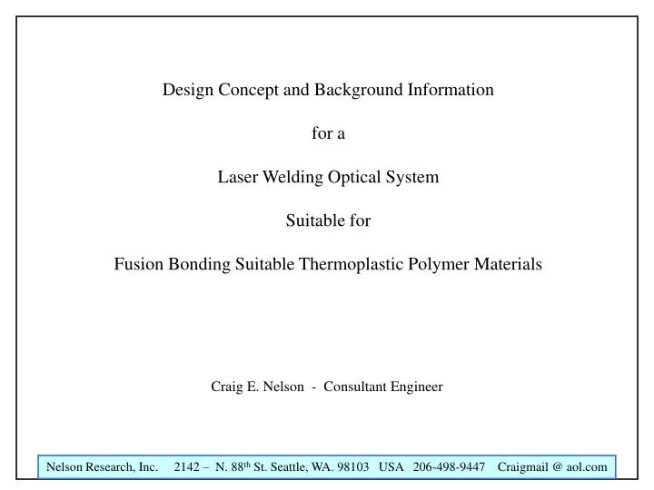
Design Concept and Background Information for a Laser Welding Optical System Suitable for Fusion Bonding Suitable Thermoplastic Polymer Materials. Craig E. Nelson - Consultant Engineer. Transmission Welding of Plastic – Method of Operation. Transmission (Overlap) Welding

E N D
Design Concept and Background Information for a Laser Welding Optical System Suitable for Fusion Bonding Suitable Thermoplastic Polymer Materials Craig E. Nelson - Consultant Engineer
Transmission (Overlap) Welding Laser welding of polymers uses almost exclusively overlap geometries. That means the laser beam penetrates the upper material and is absorbed by the lower material thus heating up the lower layer directly. This layer transports the heat indirectly via heat expansion and conduction to the upper layer so that both materials are simultaneously heated up and melted. Applying external pressure leads to a strength of the welded material which almost equals that of the base material. The benefit of transmission welding is that the weld is inside the component and thus the surface is not harmed and no micro particles are generated.
Finite Element Analysis (FEA) Results Show the Temperature Distribution During Laser Fusion Welding
Choice of polymers Generally all thermoplastics and thermoplastic elastomers can be welded to each other - and, moreover, many material combinations are also possible, provided the two melting temperature ranges overlap sufficiently and they are chemically compatible. Unlike conventional techniques there are not yet any detailed and significant charts of laser welded material combinations. The current charts on ultrasonic laser welding may be taken as a first orientation guide. Weldability is determined by different factors of the component: tensile force, compression density, surface manipulation etc. as well as by the supplier of the polymer material.
Choice of suitable laser For polymer welding using the transparent-absorbing overlap method diode lasers (808, 940 nm) and also cw Nd:YAG lasers (1064 nm ) are the most suitable lasers. Diode lasers are designed with several optimal positioned single emitters as used in CD players. An appropriate optical refocussing allows these lasers to be focussed on the same welding spot. The technical design is very compact and costs are very attractive. Due to the simple scalability, laser sources with only few Watts up to several thousand Watts can be built. A wide range of different wavelengths is available, the standard wavelengths of 808 and 940 nm have the best availability at low costs. In comparison with conventional lasers with comparable power, such as Nd:YAG lasers, the beam quality, i. e. focussability of the laser beam, is less good. For many polymer welding applications, however, this is sufficient, so that diode lasers can be used for these applications. Nd:YAG lasers are solid-state lasers which have been used in industry for more than three decades. For polymer welding, cw lasers in multi mode are used. The beam quality is considerably better even in power-optimized versions than in comparable diode lasers. Main applications are those with small focal diameters and scanner heads which require high focussability. Wavelength is here 1064 nm.
Laser Benefits Laser technology features numerous process-related advantages in comparison to conventional joining techniques, such as glueing, ultrasonic-, vibration- or (heating element) hot stamp welding. Most important here are flexibility and consistent quality of welds. The quality of a laser welding seam can usually compete with any conventional technology. Tensile shear force and pressure cycle tests show that a laser weld is at least as strong as a comparable ultrasonic welding seam. Moreover, laser welding does not generate any micro particles. This is a significant advantage in particular for fluid reservoirs and medical components. As the laser applies the melting energy tightly localized, very compact structures with welding seams extremely close to heat-sensitive components can be realized. Also, there is no melt ejection and therefore no distortion with laser welding. Another advantage is, that only as much as needs to be welded, is actually heated: ”Wywiwyw“: what you weld is what you want! Lasers work without contact and do not show any wear. The quality of the weld remains consistent and the component shows the corresponding quality. Moreover, the components do not have to be preprocessed before welding - this fact also contributes to a constant welding quality. It has been proven that the reject rate with laser welding can be reduced to a very attractive minimum compared to conventional technologies.
The Laser Welder Optical Head - Mark I Non-contacting Optical Elements with Substantial Standoff Optical Design – Single Negative Lens Craig E. Nelson – Consultant Engineer
Plane of Best Installation 8.94 mm Unmodified laser beam
About 13 mm 2.0 mm 2.25 mm Plane of Best Installation 19.25 mm Negative lens (Edmunds # Y45-380) used to “push out” the focal zone
Plane of Best Installation 19.25 mm the focal zone shows a fair amount of spherical aberration
6mm 2 mm Negative Lens Configuration with Close Focusing ( 2 mm standoff setup)
Negative Lens Long Standoff System Optical Parameters ( 13 mm standoff setup)
The Laser Welder Optical Head - Mark I Non-contacting Optical Elements with Substantial Standoff Optical Design – Two Negative Lenses
The Laser Welder Optical Head - Mark I Non-contacting Optical Elements with Substantial Standoff Optical Design – Refraction in the top layer - n = 1.6
A ray bundle that is configured to provide a plane of best installation 10mm from the convergent lens Refraction at the surface of a flat refractive element at 5 mm moves the plane of best installation “out” by about 31% for this convergent ray bundle
The Laser Welder Optical Head - Mark I Non-contacting Optical Elements with Substantial Standoff Mechanical Design
The Laser Welder Optical Head - Mark II Sapphire “Pressure Ball” Optical Element Optical Design Craig E. Nelson – Consultant Engineer
The Concept – Apply Pressure to Weld Layers Through a Ball Lens that Passes and Focuses the Laser Beam
Rc= 4.71 mm 6.35 mm Sapphire Ball 500 micron top layer A sapphire ball lens allows close in focusing with simultaneous axial pressure force
Sapphire Ball 500 micron top plastic layer Weld bond line at interface between plastic layers Here is a close-up view of the focal region where the fusion bond is made
.5 mm Focus set for 1 mm top layer 1.0 mm 1.5 mm 7.5 mm 6.35 mm 1.0 mm 2.3 mm Focus set for .5 mm top layer .5 mm
Lens and Sapphire Ball Focusing System Optical Parameters (.5 mm top layer thickness setup)
The Laser Welder Optical Head - Mark II Contacting Sapphire Ball Optical Element Mechanical Design Craig E. Nelson – Consultant Engineer
Optical Head Layout when the Focus is set for a 1 mm Thick Top Layer
Sapphire Pressure Ball Optical Head Showing Alternate Spring Design
Sapphire Pressure Ball Optical Head Showing an Extrusion Based Spring Design
Sapphire Pressure Ball Optical Head Showing an Extrusion Based Spring Design and Cutaway Type 2 Body Block