Download
1 / 73
730 likes | 928 Views
Timber Framing Code. INTRO TO ROOFING and PRELIMINARY CALCULATIONS. Previously. We looked at the subject in general Discussed assessment criteria Section 1. Scope & General Section 2. Terminology & definitions. Section 7. Roof Framing. Flowchart.

E N D
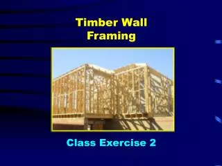
Timber Framing Code. INTRO TO ROOFING and PRELIMINARY CALCULATIONS
Previously. • We looked at the subject in general • Discussed assessment criteria • Section 1. Scope & General • Section 2. Terminology & definitions. • Section 7. Roof Framing
Flowchart • It is recommended that design starts at the roof and works down to the foundation. Although the flowchart on page 17 tells us to- • Determine wind classification. • Consider the bracing and tie-down details. • We will leave wind classification to the structures teachers • Consider bracing details after roof and wall design.
Revision Quiz 1.AS 1684 specifies the requirements for building practices for what classes of building?
4.Why is it necessary to determine the wind classification of a site prior to using AS 1684 to select section sizes of members?
5.A site may be classified as N1, N2,N3, N4, C1, C2, C3 or C4. a.What do the letters N and C indicate? b. True or false : The higher the number the greater the wind risk
Let’s start. • Remember- throughout this module we will consider Coupled roofs • With single row of underpurlin. • Without ridge struts
Roof (and ceiling) Members • Ceiling joists • Hanging beams • Counter beams • Strutting beams • Combined strutting/hanging beams • Combined counter/hanging beams • Underpurlin
Roof Members cont’d • Rafters • Hips • Ridges • Valleys
Calculations If you look at the supplement tables you see that you need to determine • Spacing of members • Spans- single or continuous • Ceiling load widths CLW • Roof area supported • Roof load widths RLW • Rafter span • Rafter overhang
Calculations • Spacing of members such as ceiling joists are measured centre to centre or “in to over"
Member sizes Remember: The flow chart dictates that we first- • Determine the wind classification • Consider position and extent of wind bracing and tie downs Let us assume- • That wind classification for all our exercises is N3 • There is sufficient room for bracing and tie-downs
Preliminary calculations • Some calculations are required before we have sufficient data to use the span tables
Preliminary calculations • You MUST have a scientific calculator. • You only need to be able to do very basic trigonometry. • You must be able to use Pythagoras theorem. • You need to be able to perform basic algebra
Preliminary calculations • What do we mean by the term ‘true length of rafter’? • We need to be able to calculate the true length of the rafter so that we can determine such things as- • The span of the common rafter • RLW • Rafter overhangs • Areas supported
Trigonometry • Comes from the Greek words ‘Trigon’ meaning triangle and ‘metre’ meaning to measure. • Trigonometry is based on right angled (900 )triangles. • It involves finding an unknown length or angle, given that we know a length or an angle or various combination of known and unknown data. • We will also use the “Pythagoras” theorem
Trig ratios • The 3 basic trig ratios are • Sine (sin) • Cosine (cos) • Tangent (tan)
Trigonometry • The ratios are related to parts of the right angled triangle • The ‘Hypotenuse’ is always the longest side and is opposite the right angle. • The other two sides are either the ‘opposite’ or the ‘adjacent’ depending on which angle is being considered.
Trigonometry • Sin =opposite ÷ hypotenuse • Cos = adjacent ÷ hypotenuse • Tan = opposite ÷ adjacent OR • S= O÷H • C= A÷H • T= O÷A
Trigonometry Some students remember this by forming the words- • SOH CAH TOA • Or by remembering • Some Old Hounds • Can’t Always Hide • Their Old Age
The Pythagoras theorem • The square on the hypotenuse equals the sum of the squares on the other two sides. • Or A2 = b2 + c2
Roofing calculations. • If we know the roof pitch. • And the run of the rafter. • We will use the term RUN of rafter rather than half span. • We can use trigonometry and Pythagoras to find the true length of the rafter • And it’s overhang.
True length of the common Rafter Centre of ridge Outside edge of top plate Rafter length underpurlin Rise of roof overhang Run of rafter
NOTE! • We are not calculating an ordering length. • We require the length from ridge to birdsmouth. • You may know this as the set out length • We need to find the Eaves overhang separately
Problem • Calculate the true length of the rafter • Pitch is 270 • Run of rafter is 4000
Example:Method 1. (using Tan) • Trade students may be more comfortable with this method • Find the Rise per metre of C.Raft • Find the True length per metre of C.Raft • Multiply TLPM x Run= True length of rafter.
Method 1. (using Tan) • Rise per metre run = Tan 270 = 0.5095 = 0.510 • T.L. per metre CR = √ R2 + 12 = √ 0.5102 + 12 = √ 1.260 = 1.122m • T.L.C.R. = T.L per metre X run = 1.122x 4.0 = 4.489m
Method 2. Using Cosine (Cos) • Pitch is 270 • The run is 4.0m • Cos 270 = adjacent ÷ hypotenuse = run ÷ rafter length • Rafter length = run ÷ cos 270 = 4.0 ÷ 0.8910 = 4.489m
Exercises • Calculate the following rafter lengths. (choose either method) • Pitch 370 , Run 3.750m • 4.696m • Pitch 230 , Run 4.670m • 5.073m • Pitch 19.50 , Run 2.550m • 2.705m
True length of eaves overhang. • Firstly you must be aware of the difference between eave width and eaves overhang. • For a brick veneer building with an eaves width of 450mm; the actual width to the timber frame is 450 + 150mm for brick and cavity = 600mm
True length of eaves overhang. • The true length of the eaves overhang is the measurement ‘on the rake’ from the ‘x y’ line to the back of the fascia along the top edge of the rafter. • It can be calculated the same way you calculate you calculated the rafter length
True length of the common Rafter Centre of ridge Outside edge of top plate Rafter length underpurlin Rise of roof overhang Run of rafter
Student exercises 2. • Calculate the true length of eaves overhang for each of the following (all brick veneer) • Pitch 270, eaves width 450mm • .673m • Pitch 370 , eaves width 500mm • .814m • Pitch 230 , eaves width 480mm • .684m
Span of the common rafter. • The ‘Span of the rafter’ is the actual distance on the rake between points of support.
Span of the common Rafter Centre of underpurlin span Outside edge of top plate span overhang
Span of the common rafter. • Span of rafter is the true length of the rafter divided by 2 • That is:- from our previous example = 4.489 ÷ 2 = 2.245m
Student exercises 3. • Calculate the span of the common rafter for the 3 roof pitches from previous exercise.
Exercises (calculate span) • Pitch 370 , Run 3.750m • 4.696m / 2 = 2.348m • Pitch 230 , Run 4.670m • 5.073m / 2 = 2.537m • Pitch 19.50 , Run 2.550m • 2.705m / 2 = 1.353m
Fan struts • We can make more economical use of underpurlin by using fan struts. • The fan strut does not increase the allowable span of the underpurlin. • It enables the points of support (walls or strutting beams) to be further apart
Fan struts • To estimate the spread of the fan strut we make 3 assumptions • The underpurlin is in the centre of the rafter length. • The plane of the fan strut is fixed perpendicular to the rafter. • The fans are at 450