Download
1 / 15
150 likes | 337 Views
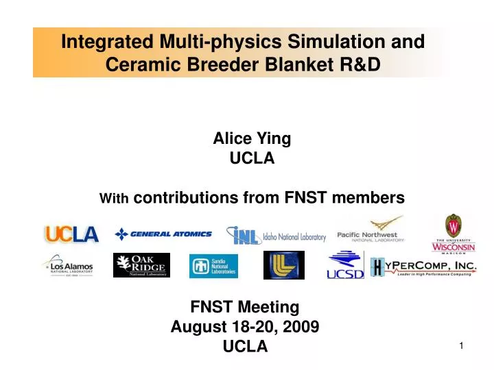
Integrated Multi-physics Simulation and Ceramic Breeder Blanket R&D. Alice Ying UCLA With contributions from FNST members . FNST Meeting August 18-20, 2009 UCLA . Outline. Status on Integrated Multi-physics Simulation For both Liquid and Ceramic Breeder Blankets

E N D
Integrated Multi-physics Simulation and Ceramic Breeder Blanket R&D Alice Ying UCLA With contributions from FNST members FNST Meeting August 18-20, 2009 UCLA
Outline • Status on Integrated Multi-physics Simulation • For both Liquid and Ceramic Breeder Blankets • Currently its development serves an Ad-Hoc Design Analysis Tool • Ceramic Breeder Blanket R&D • Design Analysis (mainly for TBM) • R&D • Mainly on the modeling development (small experiments planned aiming to provide data for code validation) • Pebble bed thermo-mechanics • Tritium permeation and purge gas conditions
Integrated multi-physics Simulation Objectives • Integrated multi-physics simulation is necessary to model real-world situations, explore design options, and guide R&D • A plasma chamber nuclear component in a fusion environment involves many technical disciplines and many computational codes such as: • MCNP for neutronics, CFD/thermofluid codes for FW surface temperatures, and ANSYS for stress/deformation, etc. • Careful representation of a geometrically complex fusion component is essential to predict performance to a reasonable level of accuracy • Because of the complex geometry of the fusion system, these analyses should be performed in 3D with a true geometric representation in order to achieve high quality prediction. • An effective mechanism to integrate results of ongoing R&D and continuously evolve to Validated Predictive Capability for DEMO • Compiles data and knowledge base derived from many fusion R&Ds in out-of-pile facilities and fission reactors • Provides high level of accuracy, reduces substantially risk and cost for the development of complex multi-dimensional system of the plasma chamber in-vessel components for DEMO and near term fusion devices
Integrated multi-physics Simulation Basis Radioactivity Transmutation Species (e.g. T2)transport Structure/ thermo-mechanics Special module Thermo-fluid Electro-magnetics Neutronics Radiation damage rates Safety MHD Coupled effect Mesh services Adaptive mesh/ mesh refinement Data Management: Interpolation Neutral format Time step control for transient analysis Visualization CAD- Geometry Partitioning Parallelism Database/Constitutive equations Validation/Verification • A platform to streamline plasma chamber component design • Utilizing a CAD-based solid component model as the common element across physical disciplines • The multi-physical phenomena occurring in a fusion nuclear chamber system are modeled centering on CAD • Many interfaces must be designed to facilitate information transfer, execution control, and post-processing visualization
Utilizing a combination of fusion specific research codes and off-the-shelf third party software Example: MHD flows with heat transfer and natural convection computed using codes developed in the fusion community (such as HIMAG.) Traditional CFD/thermal analysis for non-conducting flows performed using off-the-shelf third party software – motivated by their speed and maturity Sample analysis codes and mesh requirements in ISPC • DAG-MCNP (Sawan’s presentation) • Assisted by CAD Translator such as MCAM • TMAP-4 • COMSOL Multi-physics Chemical modules • Utilize analogy between mass and heat transport equations and extend CFD capability to solve mass transport equations with relevant BCs
CAD model Split CAD model and fill voids MCNP model Initial DCLL MCNP Neutronics Analysis Assisted by MCAM CAD Translator Using MCNP parallel version with a shorter CPU running time Integrated into ITER FEAT 20 degree Model
Gamma Heating Neutron Heating Neutron Heating Gamma Heating Initial DCLL MCNP Neutronics Results (MCAM method) Heating Rate (W/cc) and TBR Mid-Plane TBM Radial 1st Breederlayer Neutron Heating TBM Toroidal Mid-plane Gamma Heating
He outlet He inlet Visualization is an important element in the integrated multi-physics predictive capability simulation tool DCLL He Circuit Design Analysis He Temperature He velocity above the outlet near the front He velocity above the outlet near the back He Velocity Helium circuit flow characteristics
Initial Results on the Assessment of FCI Thermal Conductivity Requirement Recall PbLi has higher temperatures than He during DEMO operations For FCI thermal conductivity = 1 W/mk Interpolated 1-D Heating profiles used in analysis How will MHD velocity profile change this requirement? (TBD)
Temperatures at Mid-plane He FCI k = 1 W/mK PbLi He PbLi DEMO TBM
HCCB TBM module (710 389 510 mm) He purge gas pipe Ceramic breeder pebbles Be pebbles Purge gas inlet RAFS FWwith He coolant channels Cooling plate He coolant manifolds for FW/Breeding zones Purge gas outlet Ceramic Breeder Blanket Design and R&D • Adopt edge-on approach • Locate welds at the back (as much as possible) • Reduce the amount of Be at the back • Assemble the blanket from pre-fabricated breeder units Acompletely assembled breeding unit to be inserted into the structural box
Predictive capability development for tritium permeation estimation and purge gas flow design • Accounting for flow, nuclear heating, and tritium production profiles - Velocity profile - Convection and conduction of heat (temperature profile) - Convection and diffusion of tritium - Isotopic swamping effect - Geometric complexity • Approach – Using COMSOL Multi-physics for fluid flow, temperature, convection and diffusion mass transport Mathematical Models • Performed benchmark problems for code and problem set-up validation using literature data and TMAP4 • FEM method (not yet available for turbulent flow analysis) • Extend a CFD/thermo-fluid code for mass transport analysis using user defined functions • Eliminate data mapping from CFD code to COMSOL • Accurate turbulent flow and heat transfer calculations
GAP element Prism element Solid Fluid C2 Face j Face i C1 Boundary 1_2 Boundary 2_1 Two Boundary Conditions Needed at the Fluid/Structure Interfaces Boundary Conditions Initial COMSOL/SCTetra results compared with existing data1 • Apply Sieverts’ law to calculate equilibrium concentration at the solid face (surface) • Discontinuity in the concentration profile at the interface • Continue diffusive flux at the normal direction of the interface T2 T 1K. Kizu, A. Pisarev, T. Tanabe,Co-permeation of deuterium and hydrogen through Pd, J. of Nuclear Materials, 289(2001) 291-302
High creep (thermal and irradiation) deformation region Elastic/Plastic deformation region Ceramic breeder T < 600 oC Be pebbles FW panel with He channels Internal cooling plate Capability to predict packed bed thermo-mechanics through-out its lifetime remains a key to the success of ceramic breeder blanket designs Much work remains to be done to establish such capability • Discrete element simulation of pebble bed provides contact forces at critical contact areas- eliminating potential design flaws Example: Pebble bed thermomechanics • Issues: • 3-D Temperature profiles • Differential thermal stress • Contact forces at contact • Plastic/creep deformation • Particle breakage • Gap formation 14 orthorhombic packing obtained numerically Plot showing how forces propagate through pebble contacts
Pebble bed Thermomechanics Progress and Plan • FEM creep contact model for single pebble has been constructed & simulated in an attempt to derive constitutive equations for use in DEM simulation (which otherwise can’t be obtained) • More analysis is needed to give better constitutive equation (compared with experimental pebble deformation data) • Plan: Conduct Creep Experiments on Pebble Bed (reconfirmation with Pebble Failure Map of correlation between single pebble failure and pebble bed loading pressure) & estimation of Stress State due to differential thermal expansion between pebble bed and the structural wall Average force at contact under various applied loads (DEM simulation- UCLA) Pebble mechanical integrity at high temperatures under compressive loads (Li2TiO3)–experiments conducted at UCLA) The forces exerted on the pebbles during the operation should be less than 15 N; or the pressure applied to the pebble bed from containing structural less than ~ 5 MPa.