Download
1 / 13
130 likes | 325 Views
Vibration analysis and noise reduction of the swinging unit. Noise components of ducted fans. Flow source Trace noise Noise of the turbulent boundary layer Noise of the separated flow region Mechanical source Noise of the drive train Noise of the excited cover Noise of the PWM control.

E N D
Noise components of ducted fans • Flow source • Trace noise • Noise of the turbulent boundary layer • Noise of the separated flow region • Mechanical source • Noise of the drive train • Noise of the excited cover • Noise of the PWM control
Flow source noises • Trace noise • Noise of the turbulent boundary layer
Flow source noises • Noise of the separated boundary layer • Proper and improper constructions for the entrance region • Laminar sublayer • Turbulent boundary layer (1) Separation bubble
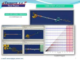
Mechanical source noises Finite element modal analysis • DOF: 162168 • N. of elements: 26824 • Solver: COSMOS Mesh: Mode shape at 48.55 Hz:
Mechanical source noises Results Number of natural frequencies in each 20 Hz range
Measurement • Four-channel-measurement • 2 accelerometers • microphone • tachometer
Measurement Zero pitch Max pitch direction 1 Max pitch direction 2
Waterfall diagrams Microphone signal compared with finite element results
Waterfall diagrams Microphone signal scaled by rpm
Waterfall diagrams The 8 kHz PWM noise appearing in the signal of the 2nd accelerometer
The 8 kHz PWM noise appearingin the signal of the microphone
Conclusions • Flow source components • Trace noise - Not significant • Noise of the turbulent boundary layer - By choosing better airfoil • Noise of the separated flow region - Proper contstruction of the entrance region • Mechanical source components • Noise of the excited cover - By increasing stiffness, rarefying natural frequencies • Noise of the PWM control - By raising controller frequency above human hearing limit Reduction or elimination of noise components Estimated total possible noise reduction: