Download
1 / 30
310 likes | 475 Views
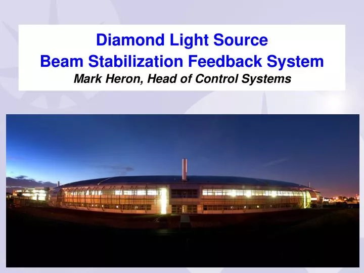
Diamond Light Source Beam Stabilization Feedback System Mark Heron, Head of Control Systems. Beam Stabilization Feedback System. Describe Orbit Stabilization feedback system applied to Diamond Storage Ring Requirements Feedback Process Feedback Controller Communication Controller

E N D
Diamond Light Source Beam Stabilization Feedback SystemMark Heron, Head of Control Systems Diamond Light Source Beam Stabilization Feedback System
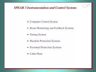
Beam Stabilization Feedback System • Describe Orbit Stabilization feedback system applied to Diamond Storage Ring • Requirements • Feedback Process • Feedback Controller • Communication Controller • Computation • Structure • Installation • Performance Diamond Light Source Beam Stabilization Feedback System
Orbit Feedback: Requirements • Overall requirement • To stabilise the electron beam in the SR to maximise photons on the experiment sample • Detail requirements for Beam Stabilization Feedback System • For the photon beam position to be reproducible fill to fill of SR • To keep the photon beam stable on the sample • To keep the electron beam stable to better than 10% of dimensions in X and Y and 10% opening angle • Over a time scale of 10s mSec to days Diamond Light Source Beam Stabilization Feedback System
Orbit Feedback: Requirements • There are a number of ongoing beam disturbances to suppress • Long term - Years/Months • Ground settling • Season changes • Medium - Days/Hours • Sun and Moon • Day-night variations (thermal) • Rivers, rain, water table, wind • Synchrotron radiation • Refills and start-up • Sensor motion • Drift of electronics • Local machinery • Filling patterns • Short - Minutes/Seconds • Ground vibrations • Traffic, Earth quakes • Power supplies • Injectors • Insertion devices • Air conditioning • Refrigerators/compressors • Water cooling • Beam instabilities in general Diamond Light Source Beam Stabilization Feedback System
Orbit Feedback: Feedback Process 7x X and 7 x Y per Cell (Total of 336) Corrector Magnets (Actuators) 7 x X and 7 x Y per Cell ( Total of 336) BPM Positions (Sensors) Diamond Light Source Beam Stabilization Feedback System
Orbit Feedback: Feedback Process • Orbit feedback is an example of a cross-directional control problem • Each sensor and actuator can be reasonably assumed to have the same dynamics • The response the linear map from actuator effort to sensor position Inverse Response Matrix Vector DC Setpoints [168] Vector BPM Setpoints [168] Regulators [168] Vector of Corr Magnet Values[168] Vector of BPM Positions[168] Vector Product Σ Σ Accelerator Diamond Light Source Beam Stabilization Feedback System
Orbit Feedback: Feedback Process • Orbit Feedback is made up of three parts • Feedback algorithm • Maintains required stability • Communication Controller • Take data from 168 x 2 BPM monitors distributed over 561m to Computation Nodes • Computation Nodes for feedback algorithm • Calculate correction values in real-time • Write correction values to the power supplies for the magnets • Realise the required performance sample rate Fs=10kHz • All of above in ~100usec Diamond Light Source Beam Stabilization Feedback System
Orbit Feedback: Feedback Controller • Response Matrix maps from actuators ( Corrector Magnets) to monitors (BPMs) • For Feedback we need to go from monitors (BPMs) to actuators ( Corrector Magnets) • Use Signal Value Decomposition of the Response Matrix to get the pseudo Inverse Responsive Matrix • This is ill-conditioned hence increases sensitivity to BPMs noise. Apply regularization to scale the singular values in calculating the pseudo-inverse • Regularized pseudo Inverse Responsive Matrix gives a robust map from monitors ( BPMs) to actuators (Corrector Magnets) Response Matrix Inverse Response Matrix Diamond Light Source Beam Stabilization Feedback System
FOFB Latencies / Bandwidth • Libera BPM Group delay of FIR: 148 µs • Libera BPM Group delay of 2 IIR: < 71 µs • Distribution of data around ring: 50 µs • DMA transfer to CPU: 49 µs • Conversion integer to float : 5 µs • Matrix multiplication 2*7*168: 4 µs • PID controller : 1 µs • Write into PS controller: 3 µs • Total: < 331 µs • Magnet/chamber estimated to have 500 Hz BW • Bandwidth of PS controller currently limits loop (set to 100Hz, but programmable) Diamond Light Source Beam Stabilization Feedback System
Orbit Feedback: Feedback Open Loop Response • Measure the plant open loop characteristic • First order response plus delay • At Ts= 100usec the delay ~4 x Ts Diamond Light Source Beam Stabilization Feedback System
E Error U Input on Process Disturbance D Y Output Σ Σ Gc Controller Gp Process R Set Point _ Internal Model Controller _ GPM Process Model Σ Orbit Feedback: Feedback Controller • Use an Internal Model Controller (IMC) which uses a process model in the feedback loop to remove process effects from the feedback loop • IMC gives a single parameter to optimise and leads to better performance and robustness than the traditional controllers (PID) on systems with a delays. • Built a model for SISO version of the system, plant model and gain controller • Optimised for stability and robustness • Determined by Gain and Phase margins Diamond Light Source Beam Stabilization Feedback System
Orbit Feedback: Communication Controller • Requirements for communications • Move the data from 168 BPMs to the Computation nodes in deterministic time • Performance • Time budget 50usec • Reliability of data transfer • Cope with data loss, but can’t retransmit • Resilience to loss of connection(s) or node(s) • Need to recover or resume operation from loss of nodes or connections • Considered using standard product or protocols • Reflective memory • MAC/IP/TCP/UDP don’ fit well with above • Commercial solutions didn’t meet requirements hence designed the Communication Controller Diamond Light Source Beam Stabilization Feedback System
Orbit Feedback: Communication Controller • Low latency, high reliability communication network. • Utilise the available Xilinx FPGA Rocket IO interface on Libera BPM. • Designed a packet forwarding Communication Controller in VHDL • Each Node is connected to at least 2 other Nodes • At start of frame, a Node (Libera BPM unit) forwards its data on each link • All data received on any input link forwarded once on all outputs • Same basic design used inside Libera BPM and inside Computation Node receiver Diamond Light Source Beam Stabilization Feedback System
Orbit Feedback: Communication Controller Define communication packet 30 bytes SOP 20 Bytes data CRC32 EOP idle • Bit rate of 2.5Gbps gives link speed incl. 8b/10b = 250MB/s • Packet transmission time for 30 Byte @ 250MB/s = 120ns • Minimal total transmission time 2 planes (168 * 120nsec) = 20.16us Packet payload (20 Bytes) • 32 bit ID, time frame count, status, flags • 32 bit x-Position [nm] • 32 bit y-Position [nm] • 32 bit BPM Sum • 32 bit Time Stamp [nsec] Packet Framing (10 Bytes) • 16 bit SOP • 32 bit CRC32 • 16 bit EOP • 16 bit idle Diamond Light Source Beam Stabilization Feedback System
Communication Frame No 1 COMPUTE NODE ALL BPM DATA COMPUTE NODE ALL BPM DATA BPM 1 DATA BPM 2 DATA BPM 3 DATA BPM 4 DATA Click to start Click to finish Diamond Light Source Beam Stabilization Feedback System
Communication Frame No 2 COMPUTE NODE ALL BPM DATA COMPUTE NODE ALL BPM DATA BPM 1 DATA BPM 2 DATA BPM 3 DATA BPM 4 DATA Click to start Click to finish Diamond Light Source Beam Stabilization Feedback System
Communication Frame No 3 COMPUTE NODE ALL BPM DATA COMPUTE NODE ALL BPM DATA BPM 1 DATA BPM 2 DATA BPM 3 DATA BPM 4 DATA Click to finish Click to start Diamond Light Source Beam Stabilization Feedback System
Communication Frame No 4 COMPUTE NODE ALL BPM DATA COMPUTE NODE ALL BPM DATA BPM 1 DATA BPM 2 DATA BPM 3 DATA BPM 4 DATA Click to finish Click to start Diamond Light Source Beam Stabilization Feedback System
Orbit Feedback: Communication Controller Computation Node BPM Monitors One Cell • Actual network is connected as Torus • Data distribution < 40usec • Robust to loss of link(s) or node(s) • With loss of links or nodes the propagation delay increases but with 50usec budget . Diamond Light Source Beam Stabilization Feedback System
Orbit Feedback: Computation • Data move from Communication Controller interface into processor memory • Computation aspects breaks down into 3 parts • Mapping from monitor to actuator space • Matrix multiplication • Appling the IMC regulator • Realised as a 5th order IIR on each of 168 x 2 actuator inputs • Multiply accumulate • Appling rate of change limiter and bounds checking to preserve the beam and enable smooth starting and stopping • Logic and arithmetic • Data move from processor to Power Supplies. Diamond Light Source Beam Stabilization Feedback System
Orbit Feedback: Computation • Use MVME5500 for embeded VME Systems • Features • 1GHz MHz MPC7455 PowerPC Processor • Cache 32K L1, 256K L2, 2 MB L3 • Gigabit Ethernet and Fast Ethernet Port • Two PCI 64-bit/66 MHz PMC-Sockets • To interface Communication Controller • AltiVec Coprocessor • Fixed-length vector operation • Single Instruction Multiple Data • Optimized for digital signal processing • Multiply, Multiply-accumulate • 2.2 Gigaflops/sec • Use VxWorks as RTOS Diamond Light Source Beam Stabilization Feedback System
Orbit Feedback: Computation Inverse Response Matrix Correctors BPM • Using AltiVec processor • Full Response Matrix x2 multiplication take 96 usec • Partition the problem • Calculate 1/24th of the corrector values ie one Cells worth in 4usec • Regulation takes 1usec on PPC processor • But requires 24 processors boards • Fits well with the distributed nature of the problem = 168 168 * Sub Matrix of Inverse Response Matrix Correctors BPM 7 = 168 * Diamond Light Source Beam Stabilization Feedback System
Orbit Feedback: Structure (one of 24 cells) Controls Network Event Network PS VME crate PMC Rocket IO FB Processor PSU IF PSU IF Processor Event Rx … PSU 1 PSU 14 14 Corrector PSUs eBPM eBPM eBPM eBPM eBPM eBPM eBPM Cell -n Cell +n Cell +m Cell -m Diamond Light Source Beam Stabilization Feedback System
Orbit Feedback: Installation (one of 24 cells) Computation Node Corrector power supplies BPM Monitors Diamond Light Source Beam Stabilization Feedback System
Orbit Feedback: Controller Performance Diamond Light Source Beam Stabilization Feedback System
Orbit Feedback: Performance 60mA Suppression of beam motion Diamond Light Source Beam Stabilization Feedback System
Orbit Feedback: Performance Diamond Light Source Beam Stabilization Feedback System
Communications Controller Availability • The Diamond Communication controller is now being used on Soleil, Delta and ESRF • Its available from Diamond (without support) or from ITech as an option on the Libera BPM with commercail support Diamond Light Source Beam Stabilization Feedback System
Acknowledgement • This is the work of many people. • Including Diamond Control Systems Group, Steven Duncan (Oxford University), Leo Breuss (Super Computing Systems) and others. Diamond Light Source Beam Stabilization Feedback System
Questions? Diamond Light Source Beam Stabilization Feedback System