Download

1 / 27
1.41k likes | 3.3k Views
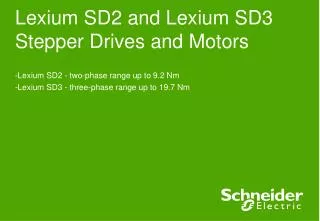
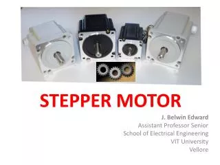
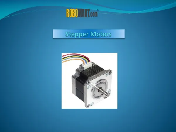
Stepper Motors. Motors. coils of conductive wire magnetic fields rotational motion except for linear induction motor everywhere from the very large (LRT) to the very small (toys) electrical energy converted to mechanical. Stepper Motors.

E N D
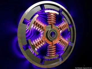
Motors • coils of conductive wire • magnetic fields • rotational motion • except for linear induction motor • everywhere from the very large (LRT) to the very small (toys) • electrical energy converted to mechanical
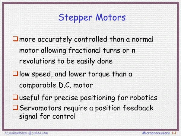
Stepper Motors • more accurately controlled than a normal motor allowing fractional turns or n revolutions to be easily done • low speed, and lower torque than a comparable D.C. motor • useful for precise positioning for robotics • Servomotors require a position feedback signal for control
Stepper Motor Types • Variable Reluctance • Unipolar/Bipolar Permanent Magnet
Variable Reluctance Motors • This is usually a four wire motor – the common wire goes to the +ve supply and the windings are stepped through • Our example is a 30o motor • The rotor has 4 poles and the stator has 6 poles • Example
Variable Reluctance Motors • To rotate we excite the 3 windings in sequence • W1 - 1001001001001001001001001 • W2 - 0100100100100100100100100 • W3 - 0010010010010010010010010 • This gives two full revolutions
Unipolar Motors • This is usually a 5 or 6 wire motor – with a centre tap on each of the two windings – the two taps are typically wired to the +ve • Our example is a 30o motor • The rotor has 6 poles and the stator has 4 poles • Example
Unipolar Motors • To rotate we excite the 2 windings in sequence • W1a - 1000100010001000100010001 • W1b - 0010001000100010001000100 • W2a - 0100010001000100010001000 • W2b - 0001000100010001000100010 • This gives two full revolutions
Unipolar Motors • To rotate we excite the 2 windings in sequence • W1a - 1100110011001100110011001 • W1b - 0011001100110011001100110 • W2a - 0110011001100110011001100 • W2b - 1001100110011001100110011 • This gives two full revolutions at 1.4 times greater torque but twice the power
Enhanced Waveforms • better torque • more precise control
Unipolar Motors • The two sequences are not the same, so by combining the two you can produce half stepping • W1a - 11000001110000011100000111 • W1b - 00011100000111000001110000 • W2a - 01110000011100000111000001 • W2b - 00000111000001110000011100
Motor Control Circuits • Fundamentally a circuit as below is required
Motor Control Circuits • We must deal with the inductive kick when the switches are turned off. We can shunt this using diodes.
Motor Control Circuits • In order to interface the stepper motor with a μP (or similar) we need a TTL compatible circuit. The 5v control should be well regulated. The motor power will not require regulation.
Motor Control Circuits • For low current options the ULN200x family of Darlington Arrays will drive the windings direct.
Terminology • Steps per second, RPM • SPS = (RPM * SPR) /60 • Number of teeth • 4-step, wave drive 4-step, 8-step • Motor speed (SPS) • Holding torque
Vector Generation • Hardware solutions • Logic design • State machine • Software solutions • Microprocessor and output ports • timing