Download
1 / 26
270 likes | 276 Views
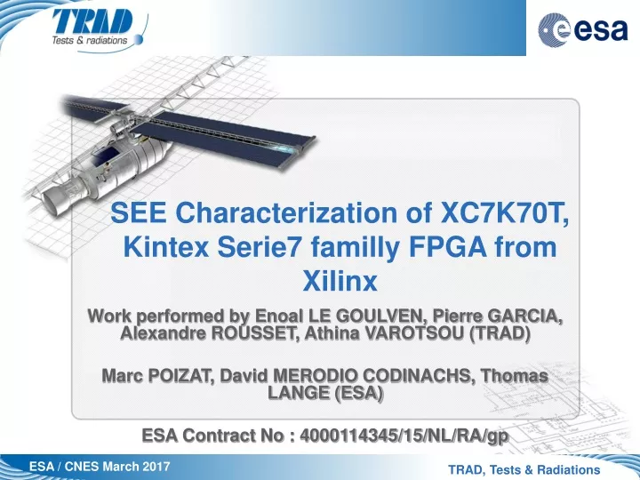
SEE Characterization of XC7K70T, Kintex Serie7 familly FPGA from Xilinx. Work performed by Enoal LE GOULVEN, Pierre GARCIA, Alexandre ROUSSET, Athina VAROTSOU (TRAD) Marc POIZAT, David MERODIO CODINACHS, Thomas LANGE (ESA) ESA Contract No : 4000114345/15/NL/RA/gp. Outl ine. Aim of this study

E N D
SEE Characterization of XC7K70T, Kintex Serie7 familly FPGA from Xilinx Work performed by Enoal LE GOULVEN, Pierre GARCIA, Alexandre ROUSSET, Athina VAROTSOU (TRAD) Marc POIZAT, David MERODIO CODINACHS, Thomas LANGE (ESA) ESA Contract No : 4000114345/15/NL/RA/gp
Outline • Aim of this study • SEE testing • Device description • Beam description • Test bench overview • For each design tested • Test method • Test results • Conclusion
Aim of this study • The aim of this study is to test a new technology of FPGA (28nm) in Latch Up, Upset and Functional Interrupt under Heavy Ions beam.
Component preparation • Flip chip die • Die directly interfaced on the PCB package • Reduce thickness of the die • Range to reach the active zone ≈ 60µm TOP XC7K70T-1FBG484C-Cross-section Active zone of the die Metallic ball
Beam description : RADEF • RADEF, Finland • Beam time : 20h • Active zone is at approximately 60µm. Xenon range from 89µm RADEF facility validated for this test
Test Bench - Hardware FPGA Board FPGA Board USB USB PC for storage and PC for storage and visualisation visualisation and and configuration configuration output output signals signals DUT Power Power Supply Supply GUARD SYSTEM GUARD SYSTEM GUARD SYSTEM Signals Signals high end modular power supply high end modular power supply Power Power Supply Supply GPIB IEEE488 GPIB IEEE488 Signals Signals SEL Curves SEL Curves SEL Curves Current Current Consumption Consumption test test VIRTEX4
Test Bench – At a glance • Single Event Latch Up (SEL) Temperature : +85°C Fluence : 1E7 #/cm2 14 power supplies monitored : - 2 Guard System Latch Up detection - BILT Current monitoring during irradiation - For each power supply Compliance at 1A • Single Event Upset and Functional Interrupt (SEFI) Temperature : Ambiant Fluence : 1E6 #/cm2 3 test designs and results
Single Event Latchup : Test Results • No SEL was observed • BUT current increased on VCCAUX, VCCINT, VCCBRAM, MGTAVCC, VCCCO_13, VCCO_15, VCCO_33 until compliance (1A)
Single Event Upset and Functional Interrupt • Three different designs: • Shift Registers • Block Memory • 32-bit Counter, developed and provided by Thomas Lange and David Merodio Codinachs from ESA
Single Event Upset and Functional Interrupt LVCMOS 3.3V Or DDR 3.3V Or LVDS 2.5V 100MHz 200MHz • Design 1 : Shift register chain • 9 shift register chains with various configurations : • Input clock 200MHz / Input Data 100MHz (9 chains) • Some chains has different output level technologies • Inverter chain (X4) has been added on various paths • For chains no.8 and no.9, 200 MHz clock has been generated through PLLx10
Single Event Upset and Functional Interrupt • Design 1 : Shift register chain 1 • Filling at least 40% of the reconfigurable blocks 2 3 4 5&6 7 8&9
Single Event Upset and Functional Interrupt Clock 200MHz Clock Registers Output 100MHz input 100MHz Detected SEU • Design 1 : Shift register analysis • The Virtex4 board was generated for each chain, a common external clock of 200 MHz + input square signal of 100MHz. • The output of each shift register chain was checked by the Virtex4 board • When an error is detected, an SEU is counted • When there is more than one consecutive error, a long SEU is counted • If 50 consecutives SEU are observed, a SEFI is counted
Single Event Upset and Functional Interrupt • Design 1 : Shift register results • SEE detected on shift registers application: • Mainly SEFI was detected. • SEUs and long SEUs was observed mainly on chain no. 8. • Events occured at same time on chains no. 8 and no. 9. These common events may be due to disruption in PLLx10.
Single Event Upset and Functional Interrupt • Design 1 : Shift register Results
Single Event Upset and Functional Interrupt • Design 1 : Shift register Results • The SEFI sensitivity is a bit higher than the SEUs and long SEUs sensitivity
Single Event Upset and Functional Interrupt • Design 2 : Block memory (BRAM) • 36 Kbits Block RAM – 4096 address bits and 9 data bits • All memory will be written with two patterns 0xAA for odd address and 0x55 for even address (checkerboard pattern) • Various read/write cycles has been performed in order to classify errors into 3 types • Event classification: • Transient (error type 1) • Upset (error type 2) • Stuck bit (error type 3)
Single Event Upset and Functional Interrupt • Design 2 : Block memory / Results • SEE detected on BRAM: • No MBUs was detected • No Type 1 SEU was detected • SEUs was detected of Type 2 and 3 (Stuck Bit), mainly Type 2 • Few SEFI was detected
Single Event Upset and Functional Interrupt • Design 2 : Block memory / Results • A strong SEU sensitivity up to a LET of 1.83MeV, in spite of only one BRAM was used
Single Event Upset and Functional Interrupt • Design 3 : 32-bit counters (ESA design) 32 • All the n « 32-bit counters » were initialized with different values • At one point, values from counters were captured by the registers • The snapshot controller allows to recover the data from the counters, then send it to one register output at a time 32 32 32
Single Event Upset and Functional Interrupt • Design 3 : 32-bit counters (ESA design) • The Virtex4 board was comparing the 32-bit data output with internal counter every two clock cycles • If 1 bit in the output word is wrong then 1 SEU is counted • If several bits in the output word are wrong then 1 MBU is counted • If 50 consecutive SEUs or MBUs are observed then 1 SEFI is counted
Single Event Upset and Functional Interrupt • Design 3 : 32-bit counters (ESA design) • SEE detected on 32-bit Counter: • High amount SEFIs was detected up to LET of 1.83MeV.cm²/mg • Few SEUs and MBUs was detected
Conclusion • SEE characterisation • Part is not sensitive to SEL, but there were no destructive increase current during the irradiation • SEFI sensitivity depends of FPGA usage capacity, thus of memory configuration (CRAM) number used • A FPGA reprogramming process was performed after every SEFI • Proton campaign should be considered
Thank you for your attention • Any question ?