Download
1 / 14
150 likes | 335 Views
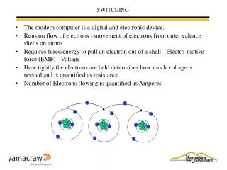
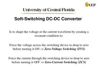
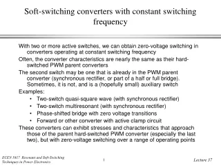
Soft-switching converters with constant switching frequency. With two or more active switches, we can obtain zero-voltage switching in converters operating at constant switching frequency Often, the converter characteristics are nearly the same as their hard-switched PWM parent converters

E N D
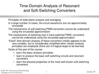
Soft-switching converters with constant switching frequency • With two or more active switches, we can obtain zero-voltage switching in converters operating at constant switching frequency • Often, the converter characteristics are nearly the same as their hard-switched PWM parent converters • The second switch may be one that is already in the PWM parent converter (synchronous rectifier, or part of a half or full bridge). Sometimes, it is not, and is a (hopefully small) auxiliary switch • Examples: • Two-switch quasi-square wave (with synchronous rectifier) • Two-switch multiresonant (with synchronous rectifier) • Phase-shifted bridge with zero voltage transitions • Forward or other converter with active clamp circuit • These converters can exhibit stresses and characteristics that approach those of the parent hard-switched PWM converter (especially the last two), but with zero-voltage switching over a range of operating points
Quasi-square wave buck with two switches Original one-switch version • Q2 can be viewed as a synchronous rectifier • Additional degree of control is possible: let Q2 conduct longer than D2 would otherwise conduct • Constant switching frequency control is possible, with behavior similar to conventional PWM • Can obtain µ < 0.5 • See Maksimovic PhD thesis, 1989 Add synchronous rectifier
The multiresonant switch Basic single-transistor version Synchronous rectifier version
Multiresonant switch characteristicsSingle transistor version Analysis via state plane in supplementary course notes
Multiresonant switch characteristicsTwo-transistor version with constant frequency
ZVS active clamp circuitsThe auxiliary switch approach Forward converter implementation Flyback converter implementation • Circuit can be added to any single switch in a PWM converter • Main switch plus auxiliary switch behave as half-bridge circuit with dead-time zero-voltage transitions • Beware of patent issues
Forward converter implementation • Zero-voltage switching of both transistors • Resonant reset of transformer reduces transistor peak voltage, relative to traditional forward converter with auxiliary reset winding • Small increase of rms transistor current • Analysis in an upcoming lecture
Zero-voltage transition convertersThe phase-shifted full bridge converter Buck-derived full-bridge converter Zero-voltage switching of each half-bridge section Each half-bridge produces a square wave voltage. Phase-shifted control of converter output A popular converter for server front-end power systems Efficiencies of 90% to 95% regularly attained Controller chips available
Phase-shifted control • Approximate waveforms and results • (as predicted by analysis of the parent hard-switched converter)
Result of analysisBasic configuration: full bridge ZVT • Phase shift assumes the role of duty cycle d in converter equations • Effective duty cycle is reduced by the resonant transition intervals • Reduction in effective duty cycle can be expressed as a function of the form FPZVT(J), where PZVT(J) is a negative number similar in magnitude to 1. F is generally pretty small, so that the resonant transitions do not require a substantial fraction of the switching period • Circuit looks symmetrical, but the control, and hence the operation, isn’t. One side of bridge loses ZVS before the other.
Summary: recent soft-switched approaches with multiple transistors • Represents an evolution beyond the quasi-square wave approach • Zero-voltage transitions in the half-bridge circuit • Output filter inductor operates in CCM with small ripple • Circuit approaches that minimize the amount of extra current needed to attain zero-voltage switching -- these become feasible when there is more than one active switch • Constant frequency operation • Often, the converter characteristics reduce to a potentially small variation from the characteristics of the parent hard-switched PWM converter • Commercial controllers are sometimes available • Sometimes a conventional voltage-mode or current-mode PWM controller can be used -- just need to add dead times • State-plane analysis of full-bridge ZVT and of active-clamp circuits to come