Download
1 / 71
710 likes | 863 Views
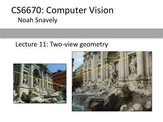
CS 636 Computer Vision. Two-View Stereo. Nathan Jacobs. Overview. recap of epipolar geometry triangulation two-view stereo readings from Szeliski Chap 11. Epipolar Geometry. => Red point lies on a line. baseline. Blue point - fixed .

E N D
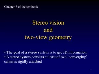
CS 636 Computer Vision Two-View Stereo Nathan Jacobs
Overview • recap of epipolar geometry • triangulation • two-view stereo • readings from Szeliski Chap 11
Robert Pless Epipolar Geometry => Red point lies on a line baseline Blue point - fixed Anepipole is the image point of the other camera’s center. All epipolar lines meet at the epipoles. Epipoles lie on the cameras’ baseline.
Robert Pless Another look (with math). • We have two images, with a point in one and the epi-polar line in the other. Lets take away the image plane, and just leave the image centers.
Robert Pless Another look (with math).
Robert Pless Another look (with math). a translation vector defining where one camera is relative to the other.
Robert Pless Another look (with math). a translation vector defining where one camera is relative to the other.
Robert Pless Another look (with math). A point on one image lies on ray in space with direction
Robert Pless Another look (with math). • Which rays from, the second camera center might intersect ray p?
Robert Pless Another look (with math). • Those rays lie in the plane defined by the ray in space and the second camera center.
Robert Pless Another look (with math). - • normal of the plane is perpendicular to both p and t. • Math fact: a x b is a vector perpendicular to a and b.
Robert Pless Another look (with math). • All lines in the plane are perpendicular to the normal to normal to the plane. • Math fact. aTb = 0 if a is perpendicular to b
Robert Pless Putting it all together. Fact: • Cameras separated by translation t • Ray from one camera center in direction p • Ray from second camera center q
Robert Pless Lets put the images back in. y x P is relative to some coordinate system.
Robert Pless x y x y • q is relative to some coordinate system, but that camera may have rotated. • So the q in the first coordinate system is some rotation times the q measured in the second coordinate system
x y x y • All three vectors in the same plane:
Robert Pless Put images even more back in. (x,y) • K maps normalized coordinates onto pixel coordinates. Given pixel coordinates (x,y), K-1 remaps those to a direction from the camera center.
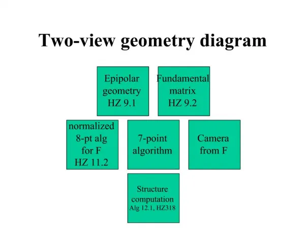
Normalized camera system, epipolar equation. “Uncalibrated” Case, epipolar equation: F is the “fundamental matrix”.
Using the equation… • Click on “the same world point” in the left and right image, to get a set of point correspondences: (x,y) that correspond to (x’,y’). • Need at least 8 points (each point gives one constraint, F is 3x3, but scale invariant, so there are 8 degrees of freedom in F).
Robert Pless So what… how to use F Potential 3d points Red point - fixed => Blue point lies on a line Given a point (x,y) on the left image, F defines the “Epipolar Line” and tells where the corresponding points must lie. How is that line defined? Only easy in homogenous coordinates!
X? x2 x1 O2 O1 Triangulation • Given projections of a 3D point in two or more images (with known camera matrices), find the coordinates of the point
X? x2 x1 O2 O1 Triangulation • We want to intersect the two visual rays corresponding to x1 and x2, but because of noise and numerical errors, they don’t meet exactly R1 R2
Triangulation: Geometric approach • Find shortest segment connecting the two viewing rays and let X be the midpoint of that segment X x2 x1 O2 O1
Triangulation: Linear approach X x2 x1 O2 O1
Triangulation: Linear approach Two independent equations each in terms of three unknown entries of X
Triangulation: Nonlinear approach • Find X that minimizes X? x’1 x2 x1 x’2 O2 O1
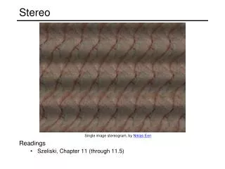
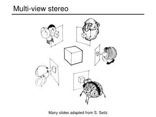
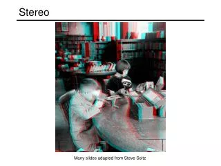
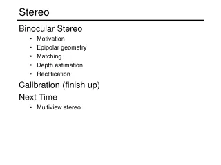
Stereo Many slides adapted from Steve Seitz
Binocular stereo • Given a calibrated binocular stereo pair, fuse it to produce a depth image image 1 image 2 Densedepthmap
Binocular stereo • Given a calibrated binocular stereo pair, fuse it to produce a depth image • Humans can do it Stereograms: Invented by Sir Charles Wheatstone, 1838
Binocular stereo • Given a calibrated binocular stereo pair, fuse it to produce a depth image • Humans can do it Autostereograms: www.magiceye.com
Binocular stereo • Given a calibrated binocular stereo pair, fuse it to produce a depth image • Humans can do it Autostereograms: www.magiceye.com
Basic stereo matching algorithm • For each pixel in the first image • Find corresponding epipolar line in the right image • Examine all pixels on the epipolar line and pick the best match • Triangulate the matches to get depth information • Simplest case: epipolar lines are scanlines • When does this happen?
Simplest Case: Parallel images • Image planes of cameras are parallel to each other and to the baseline • Camera centers are at same height • Focal lengths are the same
Simplest Case: Parallel images • Image planes of cameras are parallel to each other and to the baseline • Camera centers are at same height • Focal lengths are the same • Then, epipolar lines fall along the horizontal scan lines of the images
Essential matrix for parallel images Epipolar constraint: R = I t = (T, 0, 0) x x’ t
Essential matrix for parallel images Epipolar constraint: R = I t = (T, 0, 0) x x’ t The y-coordinates of corresponding points are the same!
X z x x’ f f BaselineB O O’ Depth from disparity meters pixels pixels meters Disparity is inversely proportional to depth!
Stereo image rectification • reproject image planes onto a common plane parallel to the line between optical centers • pixel motion is horizontal after this transformation • two homographies (3x3 transform), one for each input image reprojection • C. Loop and Z. Zhang. Computing Rectifying Homographies for Stereo Vision. IEEE Conf. Computer Vision and Pattern Recognition, 1999.
Basic stereo matching algorithm • If necessary, rectify the two stereo images to transform epipolar lines into scanlines • For each pixel x in the first image • Find corresponding epipolarscanline in the right image • Examine all pixels on the scanline and pick the best match x’ • Compute disparity x-x’ and set depth(x) = 1/(x-x’)
Correspondence search Left Right • Slide a window along the right scanline and compare contents of that window with the reference window in the left image • Matching cost: SSD or normalized correlation scanline Matching cost disparity
Correspondence search Left Right scanline SSD
Correspondence search Left Right scanline Norm. corr
Failures of correspondence search Occlusions, repetition Textureless surfaces Non-Lambertian surfaces, specularities
Effect of window size • Smaller window • More detail • More noise • Larger window • Smoother disparity maps • Less detail W = 3 W = 20
Results with window search Data Window-based matching Ground truth
Better methods exist... Ground truth Graph cuts • Y. Boykov, O. Veksler, and R. Zabih, Fast Approximate Energy Minimization via Graph Cuts, PAMI 2001 • For the latest and greatest: http://www.middlebury.edu/stereo/
How can we improve window-based matching? • The similarity constraint is local (each reference window is matched independently) • Need to enforce non-local correspondence constraints