Download
1 / 12
120 likes | 301 Views
TSF Prototype Hardware. Design Changes Since CDR Prototype tests in Manchester Towards Production Boards. SDK 11th April 2003. Specification of new TSF. ZPD requires additional fine- f output from stereo layers… this forces a rebuild of the TSF.

E N D
TSFPrototypeHardware Design Changes Since CDR Prototype tests in Manchester Towards Production Boards SDK 11th April 2003
Specification of new TSF • ZPD requires additional fine-f output from stereo layers… this forces a rebuild of the TSF. • Much of the spec stays the same, and parts of the existing design can be carried over. • Take this opportunity to make some improvements • Improve fine-f output from 5 to 6 bits • Increase number of segments output(1 per supercell => 3 per supercell pair) CDR
What we plan to do Use latest generations of devices to : • Increase density - combine functions of several devices on the original board to a single device.This is essential in some cases, eg simplifies segment selection for the ZPD output. • Increase logic speed - original TSF ran much of the logic at 30Mhz, can increase this to 60Mhz. • Use quicker signaling standards to move data faster across the board, and increase data rate across output pins CDR
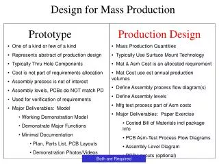
Design Changes Since CDR • Original time constraints led to design compromises at CDR • Delays in funding gave us about 9 months extra • Used this time to reconsider some of the compromises forced by our original aggressive timetable, namely • Use Virtex II rather than Virtex E chips • Drop daughtercards, opt for integrated board • Also, thoroughly re-examined parts of the original TSF design that didn’t have to change because of the new spec, to adapt them to make best use of latest technology and methodologies. • Overall dramatic reduction in cost !!!!
Data inward (Formatter) • ECL Receiver logic remains unchanged (backwards compatible) • Synchronisation FIFOs absorbed into FPGA • Memory controlled by local FPGA => neighbour data can be stored or replayed (full data sets replayed on single board standalone). • Memory can also be used for other things, eg histogramming or other monitoring of data etc would be possible - the FPGA has plenty of spare capacity (serious overkill). • Multidrop busses to engines replaced with point to point links. • Formatter FPGA selects data specifically for each engine FPGA • I/O performed on serial links
Engines • Engines are (conceptually) the least changed parts of the design ! • New engine FPGA replaces 2 of the old engine blocks, ie 6 or 7 of the old engine FPGAs • Engine FPGAs handle up to 32(27) engine cores in two pipelined banks of 16, each with a 36 bit external LUT memory accessed at 60Mhz • Wider LUT supports increased f resolution and segment selection tags • Dual ZPD output on LVDS links (on prototype) • 1st stage of BLT formatter function absorbed • I/O performed on serial links
Fast Control/Operation/DAQ • Most radical re-design of the new board • Fast Control/Operation/DAQ/ZPD&BLT Formatter merged into single chip • I/O to other chips by serial links • External memories accessed only by local FPGAs • Single external RAM used to record (or replay) ZPD&BLT output data • DAQ FIFO is implemented internally (kills 70usec problem?)
General features • Mainly unchanged from CDR • Virtex II FPGAs 3.3V I/O (only) 1.5V core. DC-DC converters • BGA memories. Can support 2.5V I/O, but stick with 3.3V. • Firmware loaded by Xilinx ACE from compact flash, select from 8 loads by rotary switch • Dual JTAG chains for FPGAs and Memories • Comprehensive boundary scan test of assembly possible with external test board. • ‘Standard’ technology 10 layer, 6thou track & gap 0.3mm drill, 100% hand routed. • Diagnostic headers to logic analyzer, also allow independent JTAG. • 1/2 depth of original board (200mm)
TSF Testing at ManchesterThe tests so far • Late Dec 1st “1 Chip” prototype. This board was tested for JTAG chains. • Just before Xmas (20th) this board was accidentally destroyed. • 1st Week of Jan second “1 Chip” board assembled. • Mid Jan 2 days of firmware tests. • FPGA loaded and talks to Mictor OK (pinout issues resolved) • Error found on an enable line, patched • Global Clock instantination problems fixed. • LVDS instatination errors fixed – LVDS loopback tests to Fast Control OK • Tests to external memory failed – suspected hardware problems • Early Feb “3 Chip” prototype assembled, and “1 chip” passes bscan. • During Feb TSF test adaptor designed & produced • Mid Feb test specification for “3 Chip and above” defined • End of Feb memory problems understood on 1 chip – VHDL corrected • Early March “3 Chip” prototype returns to assemblers for corrections • Mid March “3 Chip” board passes boundary scan, inc. I/O
TSF Testing at ManchesterBoundary Scan • BGA footprints as used on our FPGA and memory chips are not susceptible to easy optical inspection. Boundary scan is an ideal tool to verify correct assembly. • We have a JTAG Technologies system, comprising test developer software with a 4 port 3V3 boundary scan controller • We had planed to use this as a tool for testing the production boards – lwe were reluctant to use it for the partially populated prototypes because of the extensive low level editing of the netlist & configuration files this requires. However, prompted to use the system to investigate the suspected hardware faults on the “1chip” prototype. • TSF test adaptor developed which allows full testing of I/O path by boundary scan tools. • Boundary scan knows nothing about special I/O standards – this leads to problems with the LVDS signals – pairs driven by discrete drivers cannot be tested (boundary scan is NOT a substitute for firmware testing)
TSF Testing at ManchesterProduction/Repair Test Plans • 1st test of newly assembled production boards will be boundary scan. Tests ready (will have to be adapted to final netlist, few days work). The hardware required for external I/O tests is ready. • 2nd test is a firmware based ‘internal test’. This tests internal connections at full speed and above. It will always be possible to run these tests on the board (will occupy one of the firmware ‘slots’). Firmware specified and being prepared. • 3rd test will be firmware tests that require the test adaptor hardware, specifically to test the ZPD output and fast control I/O. Could also be used for pattern testing in experiment (eg TSFi/ZPDi/ZPD in corresponding test mode ??). Firmware specified and being prepared.
Steps towards Production • So far we have only seen minor faults on the prototypes... • An enable the wrong polarity • Error in Mentor map file inverting an LVDS pair • Some small improvements in mind (tinkering) • Some design issues (luxury items) need to be resolved • LVDS Muxes on ZPD output • “Auxiliary” logic on some I/O (BLT, Dlink) • No known deficiencies in the hardware resources required by the Firmware... (ie design is “fit for purpose”) • Low level hardware testing by boundary scan in place. • However, the next two months are critical…..