Download
1 / 15
150 likes | 156 Views
Learn how to represent software designs using different viewpoints, such as structural, functional, behavioral, and data modeling representations. These representations allow you to ignore implementation details and focus on higher-level abstractions. By using design representations, you can see the big picture, communicate with others, and measure various quality attributes.

E N D
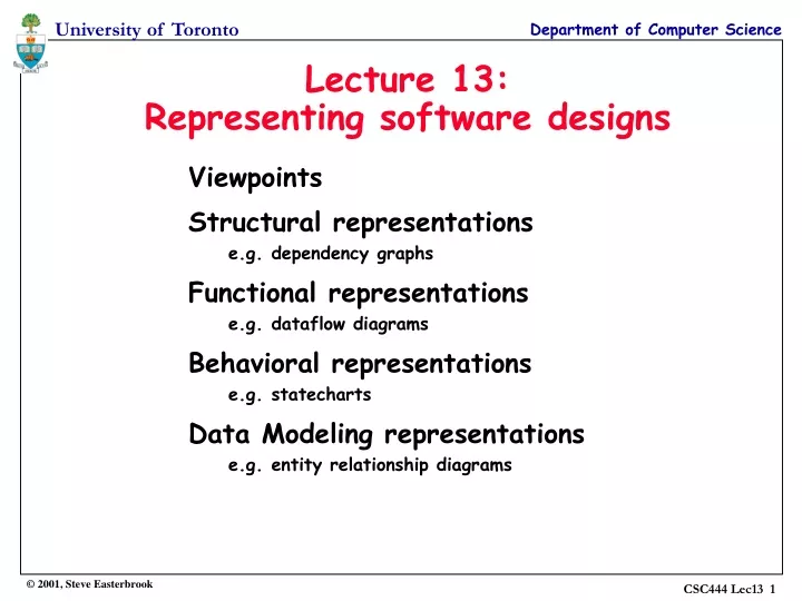
Lecture 13:Representing software designs Viewpoints Structural representations e.g. dependency graphs Functional representations e.g. dataflow diagrams Behavioral representations e.g. statecharts Data Modeling representations e.g. entity relationship diagrams
Representing Designs From abstractions to systems abstractions allow us to ignore implementation details of procedures and data structures for large systems we need to abstract away even more detail we need to represent higher level abstractions Design representations will: help us to see the big picture allow us to communicate our designs with others customers, managers, other developers, … people with varying technical expertise allow us to measure various quality attributes completeness, consistency, complexity, …
Source: Adapted from Easterbrook & Nuseibeh, 1996 Viewpoints (a.k.a. “projections”) A viewpoint tells you which details you can ignore when forming an abstraction defines which details are relevant and which are not a viewpoint has: an owner (the person interested in this abstraction) a domain (the area of interest) a representation scheme Example: Building a house Useful viewpoints: the architect’s viewpoint (plan views, elevations, etc) the plumber’s viewpoint (routing diagrams for pipework, fittings layouts, etc) the electrician’s viewpoint (wiring diagrams, etc) the buyer’s viewpoint (artist’s impression, floorplans, etc) etc… These must all be consistent eventually! Viewpoints can overlap Some aspects of a design are common to several viewpoints
Key Software Design Viewpoints Source: Adapted from Budgen, 1994 Structural viewpoints domain: static properties (structure) of the software representations: structure charts, dependency graphs, etc. Functional viewpoints domain: the tasks performed by the software, information flow representations: dataflow diagrams, procedural abstractions, etc. Behavioral viewpoints domain: cause and effect within the program representations: state transition diagrams, statecharts, petri nets, etc. Data-modeling viewpoints domain: the data objects and the relationships between them representations: entity relationship diagrams, object hierarchies Ownership? Each of these viewpoints will be of interest to different people e.g. structural viewpoints are of interest to managers for planning purposes e.g. functional viewpoints are of interest to requirements analysts and users
Notational forms Text often hard to see the big picture natural language is ambiguous best used in small chunks (e.g. for executive summaries) Diagrams good for showing relationships and structure… …if they’re kept simple: small number of symbols (e.g. 2 types of box, 2 types of arrow) must represent an abstraction (e.g. a flow chart contains nearly all the detail of code, so is not an abstraction) should be easy to sketch informally! Mathematical Expressions (formal specifications) very precise, very concise but require much training cannot (yet?) express all viewpoints (e.g. timing is difficult to express)
See also: van Vliet 1999, section 11.1.5 and 11.2.2 Structural notations Example notations Structure charts hierarchical decomposition of program Dependency graphs show the (static) control flow Objects modeled usually program components compilation units, modules, procedures … Relationships modeled structural relationships between components static relationships only “calls/controls” “uses” … Note: structural notations deal with structure of the program, not structure of the data.
p r e q e d See also: van Vliet 1999, pp311-314 The Dependency Graph Key procedure data abstraction ‘uses’ ‘weakly uses’ (refers to but does not use) Notes: all edges must be directed all nodes must be labeled with the name of the procedure only one edge between any two nodes (no matter how many times the procedure is called) recursive procedures (& data abstractions) use themselves Useful for: debugging, integration, measuring coupling p
Functional notations See also: van Vliet 1999, sections 11.2.1 and 11.2.2 Objects modeled Program components modules, procedures, Processes these do not necessarily correspond to components of the program Relationships modeled information flow inputs and outputs “communicates with”. “sends data to” “received data from” Example notations Dataflow diagrams show processes that transform data Procedural abstractions (although these combine structural viewpoint info too!) Pseudo-code
1. determine form of travel 2. check schedule 3. reserve seats 4. issue tickets Fare tables Timetables The Dataflow Diagram (DFD) See also: van Vliet 1999, pp322-325 Key process dataflow (no control implied) data store external entity system boundary customer query Notes: every process, flow, and datastore must be labeled representation is hierarchical each process will be represented separately as a lower level DFD processes are normally numbered for cross reference processes transform data can’t have the same data flowing out of a process as flows into it customer travel request schedule proposed itinerary proposed itinerary booking system booking request fares booked itinerary tickets booking confirmation booking system customer
See also: van Vliet 1999, sections 9.3.2 and 12.2.2 Behavioral notations Statecharts like an STD but with superstates and conditional transitions Petri nets for modeling process synchronization Objects modeled Dynamic properties events, states, actions, conditions Relationships modeled cause and effect sequencing / parallelism Example notations State Transition Diagrams model the program as a finite state machine
Statecharts Source: Adapted from Easterbrook & Nuseibeh, 1996 Notes: all states and transitions must be labeled transitions may be conditional (conditions shown in brackets) states can be grouped into superstates: transitions out of superstates may be taken from any substate transitions into superstates go to the default substate Key state transition superstate default initial state busy dial (callee idle) lift receiver dial tone ringing tone idle idle callee lifts receiver dial (callee busy) callee replaces receiver replace receiver engaged tone connected dial tone
Data modelling notations See also: van Vliet 1999, sections 9.3.1 and 12.2.1 Objects modeled any kind of data data types, objects, attributes of objects, classes, Relationships modeled compositional “part of” “consists of” classification “is a kind of” Example notations Entity Relationship Diagrams used in requirements modeling Class diagrams shows data abstraction hierarchy Note: in OOD, is used as a structural notation for the program!!!
Entity Relationship Diagram See also: van Vliet 1999, section 9.3.1 Notes: relationships relate entities, not their attributes there is no standard way to show the cardinality of relationships Key entity attribute relationship 1-to-1 1-to-many many-to-many name age film nationality star age cast cast producer year film director title
Summary Viewpoints help in creating abstractions a viewpoint is an abstraction created for a particular purpose by a particular person the viewpoint tells you what information to ignore when creating the abstraction each viewpoint has a suitable representation scheme Useful software design viewpoints: structural functional behavioral data modeling But a notation is not enough… you need a method to tell you how to use it. We’ll see some sample methods later in the course.
References van Vliet, H. “Software Engineering: Principles and Practice (2nd Edition)” Wiley, 1999. Chapter 11 covers various aspects of design, and introduces various design methods that combine these various viewpoints. Chapter 9 introduces some of the notations used in requirements engineering, while chapter 12 introduces notations used in object oriented design. Budgen, D. “Software Design”. Addison-Wesley, 1994 chapters 5 and 6 give a good overview of the idea of design viewpoints and an introduction to the more common notations Easterbrook, S. M. and Nuseibeh, B. A. “Using ViewPoints for Inconsistency Management”. Software Engineering Journal, Vol 11, No 1, Jan 1996. There is a growing body of research on how viewpoints can be used in software development to provide a foundation for tool support. This paper briefly introduces a framework for managing viewpoints, and then shows how they can be used to support evolution and consistency management in large specifications. The paper is available online at http://www.cs.toronto.edu/~sme/papers/1996/NASA-IVV-95-002.pdf