Download
1 / 63
680 likes | 1.06k Views
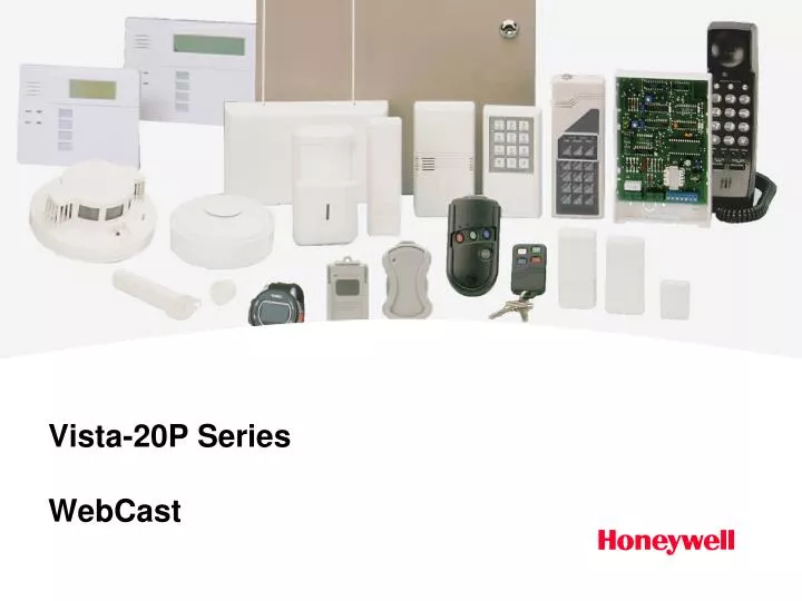
Vista-20P Series WebCast. Introduction. This course will cover programming and features on the Vista-20P throughout, with several slides that explain and compare the Vista-20P with the Vista-10P and Vista-15P. Series Comparison. Agenda. Basic Panel Features Mechanics of Programming

E N D
Introduction • This course will cover programming and features on the Vista-20P throughout, with several slides that explain and compare the Vista-20P with the Vista-10P and Vista-15P.
Agenda • Basic Panel Features • Mechanics of Programming • Programming Locations • *56 Zone Programming • *79 Output Device Mapping • *80 Defining Output Functions • Security Codes – Authority Levels & Special Features
Features • Unvacated auto stay • Cross zoning • Night arming • Carbon monoxide zone type • Dynamic zone type • Scheduling • Vent Zone • Automatic Periodic Test Command • SIA compliant
ANSI/SIA CP-01-2000 A FALSE ALARM REDUCTION standard, calls for manufacturer’s to default control panels as follows: • 60 second exit delay • 30 second entry delay plus 30 second dialer delay • Auto Stay arming enabled • Cancel verify option is enabled (displays on keypad) • Swinger suppression defaulted to 1 report per zone per armed period
Mechanics of Programming • Entering Program Mode - Use one of the following methods to enter Programming Mode: 1. Press both the [*] and [#] keys at the same time, within 50 seconds after power is applied to the Control. 2. After power-up, enter the Installer Code (4112) + 800 (If *98 was used to exit previously, method 1 above must be used to enter the program mode again) Note: When connecting a console to a defaulted panel, the console must be set to address 16. This will be covered later.
Defaulting • To default the panel you will enter: • [ * ] + 9 + 7 • Upon entering programming for the first time, it is recommended that you default the panel. • To set the panel for first time communication with Compass Downloading Software you will enter: • [ * ] + 9 + 6 • CSID = FFFFFFFF • Primary Subscriber Account Number = FFFF Note: If your downloader requires a call back phone number, refer to field *94 in your programming form.
Mechanics of Programming * 20 Installer Code [4112] Enter 4 digits, 0 – 9 To change the Installer’s Code you would enter Programming mode, then press *20, then the new code. To view what is in field 20 you would enter #20, the panel will display the location contents one digit at a time.
Mechanics of Programming • Exiting Program Mode: • *98 prevents re-entry into the Programming modes using the Installer Code. • *99 allows re-entry into the Programming modes using Installer Code (4112) + 800 • Note: If *98 is used to exit programming mode, the system must be powered down, AC and Battery, then press * & # simultaneously within 50 seconds of power up to re-enter programming.
Entry/Exit Programming [ 60,60 ] *34 Exit Delay *35 Entry Delay #1 *36 Entry Delay #2 Part. 1 Part. 2 00 - 96 = 0-96 Sec. 97 = 120 Sec. [ 30,30 ] Part. 1 Part. 2 00 - 96 = 0-96 Sec. 97 = 120 Sec. 98 = 180 Sec. 99 = 240 Sec. [ 30,30 ] Part. 1 Part. 2 Same entry choices as *35
Communication Programming • *41 Primary Phone Number • *42 Second Phone Number … *43 P1 Primary Account Number *44 P1 Second Account Number Enter up to 20 digits … Enter up to 20 digits 4 or 10 Digits [ FFFF ] 4 or 10 Digits [ FFFF ]
Communication Programming *45 P2 Primary Account Number *46 P2 Second Account Number *48 Report Format 4 or 10 Digits [ FFFF ] 4 or 10 Digits [ FFFF ] [ 7,7 ] Prim. Sec. 0 = 3+1, 4+1 Ademco L/S Stand. 6 = 4+2 Ademco Express 1 = 3+1, 4+1 Radionics Stand. 7 = 4-digit Ademco Contact ID 2 = 4+2 Ademco L/S Stand. 8 = 3+1, 4+1 Ademco L/S Stand. 3 = 4+2 Radionics Stand. 9 = 3+1, 4+1 Radionics Expanded 5 = 10-Digit Ademco Contact ID
Backup Communications *29 Long Range Radio Output [ 0 ] 0 = No 1 = Yes *29 Menu Mode for IP/GSM Enable (rev 7+) This is a Menu Mode command, not a data field, for programming IP/GSM options. Enable INT IP/GSM? Enable IP/GSM? 0= NO 1=YES 0 = no, not using either IP or GSM 1 = yes, Using IP and/or GSM module [*] to continue Programming/Diagnostics Select 1 = Prog (program the IP/GSM options) 2 = Diag (enter diagnostic mode) Do not select if using an external comm device 0 = Quit; returns to data field programming mode 1=PROG 2=DIAG 0=QUIT
*29 Menu Mode Keypad Functions Internal Device Programming Prompts [∗] = scroll the options of a particular prompt [#] = accept the entry and move to the next prompt [A] = backspace or shift-[A] for escape [B] = scroll to next prompt or shift-[B] scroll to previous prompt [C] = answer No or shift-[C] answer Yes to prompt [D] = shift key
Backup Communications *54 Dynamic Signaling Delay *55 Dynamic Signaling Priority [ 0 ] 0 = No delay (Both signals sent) 1-15 = delay times in 15 sec. increments 1 = 15 Sec. 2 = 30 Sec. Etc. Note: if *55 is set to “0”, use min. 30 sec to avoid redundant IP report. [ 0 ] 0 = Primary Dialer first 1 = IP/GSM module first
System Setup *84 Auto Stay Arm *85 Cross Zone Timer *93 Reports in Armed Period Per Zone [1] 0=no, 1=partition 1 only 2=partition 2 only, 3=both partitions If enabled, the system will automatically change AWAY mode to STAY mode if the entry/exit door is not opened and closed within the exit delay time after the user arms in AWAY mode from a wired keypad. [0] 0=15 sec. (Assign cross zones on zone list 4, with *81 Menu mode) (see program sheet for complete list of options) [1] 0=Unlimited Reports 1=1 report per 2=2 reports per
…. …. Pager Information *160 Pager 1 Phone No. Enter up to 20 digits 7-digit status code: XXX-YYYY XXX = 3-digit event code: 911 = Alarm 811 = Trouble 101 = Opening (disarm) 102 = Closing (arm AWAY YYYY = 4-digit user or zone number The first digit indicates the partition, followed by the 3-digit user or zone number. 0 = system, 1 = part 1 2 = part 2, 3 = part 3 *161 Pager 1 Characters Enter up to 16 digits • The character could be composed of: • PIN number • Subscriber account number • * (enter # + 11 to send *) • # (enter # + 12 to send #) • Pause (enter # + 13 to allow a 2-second pause)
Pager Options *162 Pager 1 Reporting Options [ 0,0,0 ] Part. 1 Part. 2 Common 0 = no report sent 1 = open/closes all users 4 = All alarms and troubles 12 = Alarms/troubles for zones entered in zone list 9 13 = Alarms/troubles for zones entered in zone list 9 and open/close for all users Pagers 2-4 are set up the same way in Locations *163 -*171
Pager Options *172 Pager Delay Option for Alarms [3] 0 = none 1 = 1 minute 2 = 2 minutes 3 = 3 minutes This delay is for ALL pagers in the system.
Configurable Zone Type Programming *182 Configurable Zone Type 90 1 2 3 4 5 6 7 8 9 10 See programming sheet for complete List of options. *183 Zone Type 90 Report Codes 90 Alarm ID XXX Trouble ID:XXX Enter the desired 3-digit Contact ID report codes for alarms and troubles occurring on zones assigned to this zone type. *184 Configurable Zone Type 91 1 2 3 4 5 6 7 8 9 10 See programming sheet for complete List of options. *185 Zone Type 91 Report Codes 91 Alarm ID XXX Trouble ID:XXX Enter the desired 3-digit Contact ID report codes for alarms and troubles occurring on zones assigned to this zone type.
Advanced User Interface Programming [1] [1] [0] [0] *189 Symphony (AUI) enable AUI 1 AUI 2 AUI 5 AUI 6 Enter each AUI’s Home partition. 0 = disabled 1 = partition 1; 2 = partition 2 3 = partition 3 (common) Note: an external power supply may be required when using AUI consoles.
Keypad Options NOTE: Options for keypad address 16 are set by the factory and cannot be changed. Each keypad must be assigned a unique address. *190 Keypad 2 Address 17 *191 – *196 Are Identical for addresses 18 – 23 respectively. [0] [0] Sound Partition/Enable 0 = no suppression 1 = suppress arm/disarm and E/E beeps 2 = suppress chime beeps only 3 = suppress arm/disarm, E/E, and chime beeps 0 = keypad disabled; 1-3 = part.no. (3=common)
Keypad Options [0] *197 Exit Time Display Interval *198 Display Partition Number (for Alpha Display Keypads) *199 ECP Fail Display 0 = no display 1-5 = seconds between display refresh [0] 0= no; 1=yes (partition number appears on Alpha Display) [0] 0 = 3-digit display (“1” + device address) 1 = 2-digit fixed-display as “91”
Table of Device Addresses All devices attached to ECP (keypad) terminals must be addressed. Depending on the device and its function the address is determined by the following:
Table of Device Addresses †† Addressable devices are identified by “1” plus the device address when reporting. Enter a report code for zone 91 to enable addressable device reporting (default = reports enabled). See field *199, mentioned earlier, for ECP Fail Display options.
*56 Zone Programming Mode 0 = no 1= yes Confirm? SET TO CONFIRM? 0= NO 1=YES 0 Enter Zone Number 01-99 = zone number 00 = quit [*] to continue Not all numbers Available. Enter Zn Num. (00 = Quit) 10 Summary Screen [*] to continue IN: L = Wireless, RF = Supervision IN: AD = Expansion, AW = Aux wired HW: RT = Hard Wire, EL = loop type Zn ZT P RC In: L 10 00 1 10 RF 1 Or Zn ZT P RC In: AD 10 00 1 10 AW: 07 Or Zn ZT P RC HW: RT 02 00 1 10 EL 1
*56 Zone Programming Mode Zone Type (ZT) 00 = Not Used 01 = Entry/Exit #1 02 = Entry/Exit #2 03 = Perimeter 04 = Interior Follower 05 = Day/Night 06 = 24-Hr Silent 07 = 24-Hr Audible 08 = 24-Hr Aux 09 = Fire 10 = Interior w/Delay 12 = Monitor Zone 14 = Carbon Monoxide 16 = Fire w/Verify 20 = Arm-Stay* 21 = Arm-Away* 22 = Disarm* 23 = No Alarm Response 24 = Silent Burglary 77 = Keyswitch 81 = AAV Mon. Zone 90-91 = Configurable 10 Zone Type Perimeter 03 * 5800 button-type transmitters only.
*56 Zone Programming Mode 1-3 = partition (3=Common) [*] to continue Partition No. (P) 10 Partition 1 Report Code (RC) 01-09, 10 for 0, 11 for B, 12 for C, 13 for D, 14 for E, 15 for F. 00 to Disable Examples: 01 00 = report code 10 13 15 = report code DF 10 Report Code 1st 01 2nd 00 10 Hardwire Type 0=EOL; 1=NC; 2=NO; 3=zone doubling (ZD); 4=double-balanced (DB). This prompt appears only for zone numbers 02-08. [*] to continue 02 Hardwire Type EOL 0
*56 Zone Programming Mode Response Time (RT) 02 Response Time 1 0 = 10mSec; 1 = 350mSec; 2 = 700mSec; 3=1.2 seconds [*] to continue Only for zones 01-08, zone 02 shown Input Device type (In) 2 = AW (Aux wired zone) 3 = RF (supervised RF transmitter) 4 = UR (unsupervised RF transmitter) 5 = Button type RF transmitter (unsupervised) 10 Input Type RF Trans 3 • Serial number Entry and Loop Number Entry • Used only when enrolling wireless transmitters. • Transmit two open/close sequences. • Manually enter the 7-digit serial number. • Press key [C] to copy the serial number previously enrolled. • [*] to continue 10 Input S/N: L A XXX-XXXX 1
*56 Zone Programming Mode Loop Number Change 10 Input S/N: L A 022-4064 ? Enter the loop number. To delete enter 0 in the loop number. [*] to continue Enroll Summary If the serial/loop number combination is not a duplicate in the system, a display showing the serial number and loop number entry will appear. [*] to continue 10 Input S/N: L A 022-4064 1 Confirm Note: This prompt will only appear if the first prompt after entering *56 was answered “YES” [*] to continue 10 XMIT TO CONFIRM PRESS * TO SKIP
*56 Zone Programming Mode Not Confirmed [*] to continue If the serial number transmitted does not match the serial number entered this prompt will appear. Entd A022-4063 Rcvd A022-4064 Summary Screen [*] to continue Zn ZT P RC In: L 10 03 1 10 RF 1
Output Device Option *177 Device Duration 1,2 (used in *80 menu mode-Device Actions 5/6) [0] [0] 1 2 0 = 15 secs 1 = 30 secs 2 = 45 secs 3 = 60 secs 4 = 90 secs 5 = 2 min 6 = 2-1/2 min 7 = 3 min 8 = 4 min 9 = 5 min # = 10 = 6 min # + 11 = 7 min # +12 = 8 min # + 13 = 10 min # + 14 = 12 min # + 15 = 15 min
*79 Menu Mode *79 Mode is used to identify available outputs that the panel can use. These outputs are actually programmed to activate and release in *80 defining output functions.
*79 Menu Mode Device Output Number 01-18 relays/X-10; 00 = Quit [*] to continue ENTER OUTPUT NO. 00 = QUIT xx This is the reference relay number as used in the system. Relays and X-10 devices are numbered 01-16. The on-board triggers are numbered 17 and 18. Output Type - This prompt appears if selecting outputs 01-16. 0 = delete 1 = relay on 4204/4229 module 2 = Powerline / X-10 [*] to continue XX OUTPUT TYPE DELETE 0 If X-10 is selected, we will use “A” prompt If relay is selected, we will use “B” prompt
*79 Menu Mode “A” Unit Number If X-10 is selected, a prompt for the unit number appears. 01-16 = predefined unit number [*] to continue XX UNIT No. yy
*79 Menu Mode Module Address “B” XX MODULE ADDR 07-15 yy Module Address 07-15 = predefined address [*] to continue
*79 Menu Mode Relay Position 1-4 = relay position [*] to continue This is the physical relay position with respect to the relay module upon which it is located. The system then returns to the Output Number prompt for programming the next device. XX REL POSITION. 1-4 zz ENTER OUTPUT NO. 00 = QUIT xx
*79 Menu Mode Output Normally Low 0=no (standard default) 1=yes [*] to continue 17 OUT NORM LOW 0= NO 1=YES 0 This prompt appears only for triggers 17 & 18. Selecting 0 (no) sets the output level normally high(open). Selecting 1 (yes) set the output level normally low(ground). Output trigger 17 (100mA max.) can be used for resetting 4-wire smoke detectors (up to 2 smokes) by connecting it to the negative power terminal of the smoke detector.
*80 Menu Mode In *80, we program relays or X-10 devices, previously defined in *79 output device mapping, to activate and deactivate. The Vista-20P allows 48 output functions to be programmed. The Vista-15P allows 24 output functions to be programmed. The Vista-10P allows 12 output functions to be programmed. Each output function determines only one action. For example: To turn a relay on and off requires two output functions.
*80 Menu Mode Output Function No. 01 – 48 output function number Enter the output function number to be defined (or 00 to exit). [*] to continue Output Funct. # (00 = Quit) 01 Summary Screen A= Output Action; E= Triggering event; P= Partition; Trig = Trigger type [*] to continue Note: A question mark in the summary screen indicates that the device number shown has not been mapped. Use *79 Menu mode to map the device. 01 A E P Trig ?00 0 0 - ZL=1
*80 Menu Mode Activated By 0 = delete (delete the output function and any previous programming; see prompt below 1 = zone list (go to “A” prompt) 2 = zone type (go to “B” prompt) 3 = zone number (go to “C” prompt) [*] to continue 01 Activated by: Delete 0 Delete? 0 = NO, 1 = YES Press 1 to delete this output definition.
*80 Menu Mode 01 Activated by: Zone List 1 “A” Zone List 1 – 8 zone list [*] to continue 01 Zn List 1 Enter Event Alarm 1 0 = restore; 1 = alarm; 2 = fault; 3 = trouble NOTE: For alarm, fault, and trouble an event on ANY Zone in the list activates the output, but ALL zones in the list must be restored before the output is restored. Press [*] to continue to the “Output Action” prompt.