Download
1 / 4
40 likes | 151 Views
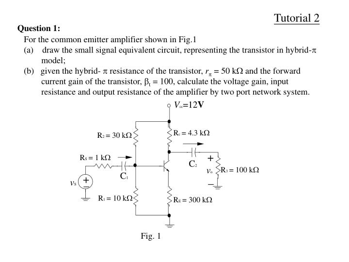
Tutorial 2. Question 1:. For the common emitter amplifier shown in Fig.1 (a) draw the small signal equivalent circuit, representing the transistor in hybrid- model;

E N D
Tutorial 2 Question 1: For the common emitter amplifier shown in Fig.1 (a)draw the small signal equivalent circuit, representing the transistor in hybrid- model; (b)given the hybrid- resistance of the transistor, r = 50 k and the forward current gain of the transistor, t = 100, calculate the voltage gain, input resistance and output resistance of the amplifier by two port network system. Fig. 1
Tutorial 2 Question 2: For the amplifier shown in Fig. 2, ignoring the effect of output resistance of the transistor, express the open loop gain and close loop gain of the amplifier in term of hybrid- parameters of the transistor, by using the two port network system. Fig. 2
Tutorial 2 Tutorial 2 Question 3: For the inverting amplifier shown in Fig. 3, if the operational amplifier has an input resistance ri, output resistance ro and open-loop gain A, determine the close loop voltage gain, input resistance and output resistance of the inverting amplifier. Fig. 3
Tutorial 2 Question 4: • For the circuit shown in Fig. 4, supposing the operational amplifier is NON-IDEAL, Determine, with the use of two port network: • the type of feedback (i.e. negative or positive, shunt or series); • the amplifier gain; • the input and output resistance. Fig. 4