Download
1 / 27
270 likes | 409 Views
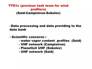
Low-tropospheric wind profilers and radio contamination issues. Wind profiler - how it works - examples Frequency issues. Dominique Ruffieux MeteoSwiss Aerological Station of Payerne. Ground-based remote sensing system, active and passive. How a remote sensing system works ?. Emission.

E N D
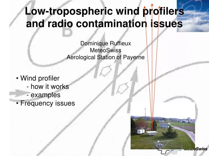
Low-tropospheric wind profilers and radio contamination issues • Wind profiler • - how it works • - examples • Frequency issues Dominique RuffieuxMeteoSwissAerological Station of Payerne
Ground-based remote sensing system, active and passive How a remote sensing system works ?
Emission An electromagnetic pulse is emitted towards the zenith and at least 2 15deg-tilted directions (North and West for ex.)
Reception The intensity of the return signal by the atmosphere depends mainly on the humidity and on the thermal gradients within the atmosphere (Cn2)
0 The frequency spectra obtained for each level are characterized by their moments: • Doppler shift • Spectral width • Noise level • Signal-to-noise ratio (SNR)
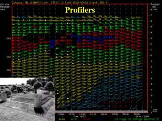
22.0 Signal processing 21.0 20.0 A succession of coherent averaging steps are followed by a Fast Fourier Transform (FFT) The result is a series of spectra defined for each level (heights) and each of the beams 19.0 18.0 17.0 16.0 15.0 14.0 13.0 12.0 11.0 Level 10.0 9.0 8.0 7.0 6.0 5.0 4.0 3.0 2.0 - + Frequency
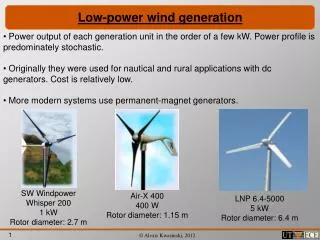
1 GHz systems (Nice) up to 5km 400 MHz systems (Nordholz) up to 16km 50 MHz systems (Aberystwyth) up to 20km
1290 MHz , 6 degree beams 15 -29dBi 30 minutes
Wind profiler data use, examples • Operational - NWP assimilation - Weather forecast - Aeronautics - surveillance of special installations • Research - Urban climatology - Complex topography - Air pollution
(1) Assimilation in real time in NWP models: - ECMWF - UK Met Office model - French model Aladin - German LM model - Swiss aLMo model - USA, Japan, ... Payerne, 23 May, 2005
(2) Weather forecasting and nowcasting - winds - fog limit - melting level Payerne, 29 January, 1997 Payerne, 23 May, 2005
(3) Aeronautics From METEO FRANCE
Leibstadt - surface - profiles Schauffhausen - surface - profiles St.Chrischona - tower Beznau - surface Goesgen - surface Uetligerg - tower Wynau - surface - profiles Stockeren - tower Bantiger - tower Muehleberg - surface Payerne - surface - profiles N 0 30 km (4) Project for a new network for the surveillance of the Swiss nuclear power plants (including three 1290 MHz wind profilers)
Research (1) Urban meteorology (BASEL) Evening (18-00 UTC)
6 November, 1999 (2) Complex topography (MAP)
(3) Air pollution (NOAA/ETL) 13-14 LST
EUMETNET WINPROFIISetting up of an operational wind profiler network in Europeincluding thirteen 1290 MHz systems (1 September 2005)
RESOLUTION COM5‑5 (WRC‑97) IMPLEMENTATION OF WIND PROFILER RADARS The World Radiocommunication Conference (Geneva, 1997), considering a) that wind profiler radars are vertically‑directed Doppler radars exhibiting characteristics similar to radiolocation systems; b) that wind profiler radars are important meteorological systems used to measure wind direction and speed as a function of altitude; c) that it is necessary to use frequencies in different ranges in order to have options for different performance and technical characteristics; d) that, in order to conduct measurements up to a height of 30 km, it is necessary to allocate frequency bands for these radars in the general vicinity of 50 MHz (3 to 30 km), 400 MHz (500 m to about 10 km) and 1000 MHz (100 m to 3 km); e) that some administrations have either already deployed, or plan to expand their use of, wind profiler radars in operational networks for studies of the atmosphere and to support weather monitoring, forecasting and warning programs; f) that the ITU radiocommunication study groups have studied the technical and sharing considerations between wind profiler radars and other services allocated in bands near 50 MHz, 400 MHz and 1000 MHz,
Notes ... d) 904 - 928 MHz: This band (center frequency 915 MHz) is designated for industrial, scientific and medical (ISM) applications in Region 2 (basically the Americas). In this area, 1 GHz wind profiler radars can be operated here. e) 1270 - 1295 MHz: In Regions 1 and 3 where the ISM band is not available, or in Region 2 where operation in the ISM band is not feasible, this radiolocation band is available for wind profiler radar operations. f) 1300 - 1375 MHz: Where neither in the ISM band nor in the radiolocation band operation is feasible, this band may be used for wind profiler radar operations.
Compatibility between GALILEO and wind profiler radars in the 1215-1300Mhz band GALILEO is the new European Satellite Navigation System • Satellite deployment 2006-2008, operational 2008, 3 x 10 satellites • E6 frequency: 1278.75 MHz, B/W: 40 MHz • E6 power level on the ground -122 dBm • How will this signal be seen by wind profiler radars ? • What are the best mitigation options ?
Various studies in Europe performed within the Electronic Communication Committee (ECC-SE39 working group) • Finnisch/Vaisala report • Roke Manor report • Deutscher Wetterdienst report • Meteofrance report • final ECC SE39 report with mitigation proposals (in final state)
(1) Interferences caused by GALILEO GALILEO signal simulation (DWD) • No coherent interferences • Incoherent interferences
Coherent interferences (further testing are expected to confirm these results)
A decrease of the NCI by a factor of 4 should result in an increase of the noise level of 6 dB Incoherent interferences
(2) Main mitigation options currently in discussion • a minor frequency shift into GALILEO signal spectral minima (E6 null), • Increasing the number of beams • a modification of the beam sequence, • a major frequency shift of the wind profiler frequency. • In case no mitigation techniques would be efficient, the wind profiler community would recommend a shift of the wind profiler frequencies down to the 0.8 – 1.2 GHz band.
Wind profilers are operational worldwide (Europe, USA, Australia, Japan, ..) Wind profilers are providing valuable information for both operational and research applications related to meteorology and climatology Low-tropospheric 1GHz systems performance will likely experience minor interference from the new GALILEO system Summary • Because of the high sensitivity of the wind profiler receiver, new types of contamination can be expected in the near future.