Download
1 / 25
350 likes | 1.03k Views
Sensors used in EFI (Electronic Fuel Injection). Dr. Shahin H. Berisha GateWay Community College Phoenix, Arizona, USA. What is EFI?. EFI is a way of delivering fuel to the engine by electronically controlling injection directly into the intake manifold near the intake valve. History of EFI.

E N D
Sensors used in EFI (Electronic Fuel Injection) Dr. Shahin H. Berisha GateWay Community College Phoenix, Arizona, USA
What is EFI? • EFI is a way of delivering fuel to the engine by electronically controlling injection directly into the intake manifold near the intake valve
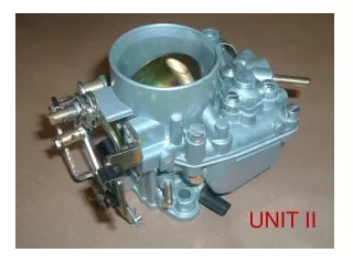
History of EFI • Carburetors are used to mix air and fuel, • In 1979/80 Toyota introduced EFI, • By 1991 the carburetor is eliminated, • Reasons for switch: • Superior emissions control, • Better fuel economy, • Improved vehicle performance
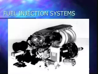
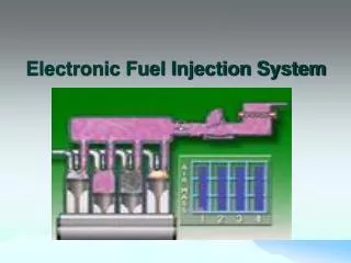
How EFI Works? • There are three sub-systems in EFI • the fuel delivery system • air induction system • the electronic control system
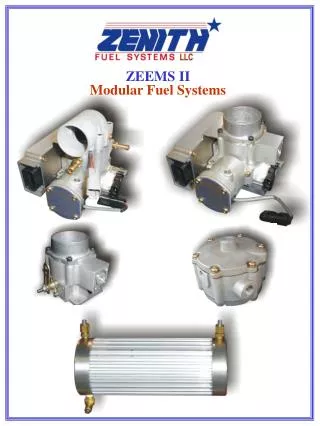
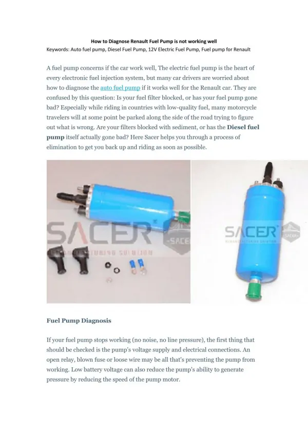
Fuel Delivery System • This system consist of the: • fuel tank, • fuel pump, • fuel filter, • fuel delivery pipe, • fuel injector, • fuel pressure regulator, and • fuel return pipe.
The Air Induction System • This system consist of the: • air cleaner, • AIR FLOW METER • throttle valve, • air intake chamber, • intake manifold runner, and • intake valve.
Electronic Control System • This system consist of the: • Various engine SENSORS, • Electronic Control Unit (ECU), • Fuel injector assemblies, and related wiring • The ECU determines precisely how much fuel needs to be delivered by the injector based on the engine SENSORS output. Injector is turned On for the precise amount of time to deliver proper air/fuel ratio to the engine.
Air enters the engine and then measured by the AIR FLOW METER, As the air flows into cylinder, fuel is mixed into the air by injector, ECU pulses the injector On and OFF. When it is ON just enough spraying of fuel occurs, to ensure ideal air /fuel ratio 14.7:1 The ECU Control delivers precise amount of fuel to the engine, The injection quantity depend on variables such as: coolant temperature engine speed (rpm) throttle angle, exhaust oxygen content. Basic Operation of ECU System
Advantages of EFI • Uniform Air/Fuel Mixture Distribution (each cylinder has its own injector), • High accurate Air/Fuel Ratio Control (better vehicle performance, better fuel economy, and emissions control) • Super throttle response, • Improved Cold Engine Startability Operation (Starting the vehicle at lower temperatures)
Sensors involved in Air Induction System • Vane Air Flow Meter - consist on the: • spring loaded measuring plate, • potentiometer attached to the plate, • volume of the air determines the position of the plate, • position of the plate determines the value of the resistance on the potentiometer, • this resistance determines the output voltage of the sensor that goes to ECU • Karman Vortex Air Flow Meter
Sensors involved in Air Induction System • Karman Vortex Air Flow Meter • the air flow generates variable frequency digital signal, • the frequency of the digital signal is proportional to air flow
Electronic Control System • This system ahs three elements: • Input Sensors, • ECU (a microprocessor) • Output
Input SensorsFirst Design Air Flow Meter • Has seven connectors, four of which are used for air flow meter, • Air flow changes the resistance of potentiometer, • This changes the voltage drop (output voltage) across the potentiometer (Vs) • Vc is used as a reference voltage because main vehicle battery Vb may change with the load.
Input SensorsSecond Design Air Flow Meter • Has seven connectors, three of which are used for air flow meter, • Air flow changes the resistance of potentiometer (r1 and r2), • This changes the voltage drop (output voltage) across the potentiometer (Vs) • Vc is used as a reference and a regulated 5V is used instead of Vb
Input SensorsKarman Vortex Air Flow Meter • A photocoupler and a mirror • a vortex generator • and IC • When air passes through the air flow meter, the vortex generator produces digital signal • Frequency of this signal is proportional to the velocity of air
Input SensorsManifold Absolute Pressure Sensoror vacuum sensor • This sensor measures intake air volume • Consist of a piezoelectric silicon chip and an IC • Comparing the perfect vacuum and pressure in the intake manifold, the resistance of the silicon chip changes, • Change in the resistance causes change in signal voltage at PIM (Pressure Intake Mainfold) on the circuit.
Water Temperature Sensor • It monitors engine coolant temperature by a thermistor with a negative temperature coefficient, • Thermistor is part of a circuit in which a voltage drop across this thermistor is monitored by ECU • As temperature goes up voltage goes down (see figure) - negative temperature coefficient
Air Temperature Sensor • Monitors the temperature of air entering intake manifold by means of thermistor • It has identical characteristics as a water temperature sensor • This sensor is needed because the pressure and the density of air changes with temperature
Throttle Position SensorOn-Off Type Sensor • This is a simple switch device that either pulls a reference voltage to ground (V = 0) - PSW position on the circuit or • sends a battery voltage signal to ECU - IDL position on the circuit • this switching action causes the voltage signal to ECU to go high when the switch contact are closed.
Throttle Position SensorLinear Throttle Position Sensor • As the throttle opens, a potentiometer circuit converts the mechanical movement of the throttle valve into a variable voltage signal, • The output voltage VTA is proportional with the throttle opening angle
Oxygen Sensors • Exhaust oxygen sensors are used to provide air/fuel ratio feedback information to ECU, • Based on this information the ratio/fuel is adjusted continuously - Closed Loop • This idea is used in a cruise control driving • If the loop is open no information is fed into ECU • This sensor is located near the exhaust and operates at temperatures above 750oF
Zirconium Dioxide Sensor • An Electro-mechanical device that compares the oxygen content of the exhaust stream with the oxygen in an ambient air sample, • This sensor act as a battery cell with two electrodes, • Output voltage is very small, • Graph shows that if air/fuel ratio is very little below or above the proper value of 14.7:1 the voltage output jumps sharply, • This is an indicator for microcomputer to activate closed loop.
Titania Oxygen Sensor • This is a variable resistor, • The value of the resistance changes as the oxygen concentration of the exhaust gas changes, • As R changes, the signal voltage at the ECU also changes, • Similar to Zirconium Sesnor, the output voltage changes rapidly if air/fuel ratio is changed.
Knock Sensor • This is a piezoelectric device that produces an output voltage under the vibration, • The amplitude and the frequency of vibration varies with the intensity of knock, • In one type of sensor the highest voltage output occurs around vibration with a frequency of 7 kHz • This variable frequency sensor is fed into ECU
Altitude Sensor • Altitude is measured based on the oxygen density • Density of oxygen in the atmosphere is lower at high altitudes • Sensor measures the atmospheric pressure which is a function of density • In higher altitudes the injection duration is shorten