Download
1 / 38
400 likes | 616 Views
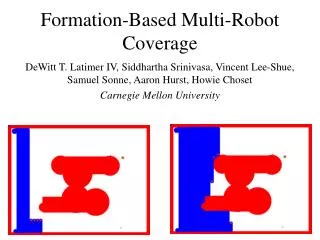
Behavior-Based Formation Control for Multi-robot Teams. Tucker Balch, and Ronald C. Arkin. Introduction. Main idea : Behavior-based approach to robot formation-keeping. The robots in this research have different IDs : heterogeneous robot.

E N D
Behavior-Based Formation Control for Multi-robot Teams Tucker Balch, and Ronald C. Arkin
Introduction • Main idea: Behavior-based approach to robot formation-keeping. • The robots in this research have different IDs: heterogeneous robot. • The formation behaviors were implemented as motor schema within AuRA, and as steering and speed behaviors within UGV demo II architecture.
Background • Why formation: • Formation in nature: • To detect predators • To efficiently forage for food • Grouping Multiple sensor • Formation in robot: • Robotic scouts also benefit by directing their sensors in different areas
Craig Reynolds pioneering work: • A simple egocentric behavioral model for flocking • The behavior consists of several separate components: 1) collision avoidance 2) Velocity matching 3) Flock centering
Tu and Terzopoulos: • Realistic simulated fish schooling. • Brogan and Hodgins: • System for realistically animating herds of one-legged agents using dynamical models of robot motion.
Wang: • Strategy for robot formation. • Individual robots are given specific positions to maintain relative to a leader or neighbor. • No obstacle avoidance and no navigation. • Chen and Luh: • The analysis of group dynamics and stability. • No obstacle avoidance and no navigation.
Mataric: • Investigated Emergent group behavior. • Simple behaviors can create an emergent flocking behavior in group • Related to Reynols’ work • Parker: • Coordination of multiple heterogeneous robots. • “Bounding overwatch”
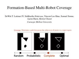
II. Approach • a) Line • b) Column • c) Diamond • d) Wedge
Formation maintenance in two steps: • Detect-formation-position: Determines robot proper position based on current data. • Maintain-formation: Generates motor command to correct robot location. • AuRA case:Motor schema control, The command is movement vector. • UGV Demo II: Separate votes are cast for steering and speed correction
Unit-center- referenced • Leader-referenced • Neighbor-referenced Formation position determined by various referencing techniques
Each robot determines the positions of its peer by direct perception of other robots. GPS, Dead-reckoning • The robot transmit their current position in world coordinates with updates as rapidly as required for the given formation speed and environmental condition. • Position errors and latency are significant factor.
Nomad 150 simulation • Motor schema implementation. • UGV implementation • Decoupling of motor control into separate steering and speed behaviors.
III Motor schema-based formation control • Motor schemas: • Move to goal, avoid obstacle, avoid robot, noise, and maintain formation. • Determined robot behavior: • Multiplying the outputs of each primitive behavior by its gain, then summing and normalizing result.
Maintain-formation schema generates a movement vector toward the desired position. • The vector magnitude depends on how far the robot is away. • Ballistic zone, controlled zone, and dead zone
The deadzone provides a stable target area. • Mobile robots require a small deadzoneto avoid oscillations about the formation position due to latency in communication. • The formation behavior is one component of the robots’ overt actions. • The resultant action depends on the relative strength of the formation behavior to the other goal-oriented behaviors.
A. Motor schema results in simulation • Georgia Tech’s mission lab robot simulation. • Five sided polygons: robot • Black circles: obstacle • Solid line: Robot path • Maintain position process: • Obstacle information request of that data send to simulation process A list comprised of angle and range data returned A robot moves and maintains the formation
Comparison of leader-referenced and unit-center-referenced diamond formation
B. Motor schema performance in turns • Evaluation in turns: • The robots commanded to travel 250m, turn right, then travel another 250m • 90 degree turn • No obstacles • 10 simulations • Robot travel 100m before the evaluation starts • 500m course evaluation excluding the 100m initial travel
Path length ratio:(average distance traveled by the four robots)/(the straight-line distance of the course) • Position error: Average displacement from the correct formation position thru the run • Time out of formation: The percentage time out of formation data
C. Motor schema performance in an obstacle field • Performance also measured for four robots navigating across a field. • Obstacles are placed randomly so that 2% of the total area is covered with 10-15m diameter obstacles. • Data from runs on 10 random scenarios were averaged for each data point.
The best performance: column formation • In most instances, unit-center-referenced formations fare better than leader-referenced formation • Overall path length for robots in a leader-referenced formation is generally longer than in unit-centered formation
D. Motor schema results on mobile robot • Two-robot team of Nomad 150 robots used: Shannon and Sally. • The robot were directed to navigate from West to East across the room. • Separate runs were conducted for each type of formation with and without obstacle.
IV. Formation control for the UGV demo II architecture • UGV Demo II is aimed at fielding a robotic scout platoon for the Army. • Each UGV is a High Mobility Multipurpose Wheeled Vehicle (HMMWV). • The UGV differs from the motor schema method. • The behaviors are coordinated by speed and turn arbiters. • Separate motor behaviors are developed for the speed and turning component of the behavior.
Non-holonomic constraint robot’s heading during formation impacts its ability to remain in position. • Positioning: • Fore-aft correction: adjust speed • Side-side correction: adjusting heading
Speed selection: • If the robot is in formation, the best speed for maintaining that formation is the current speed. • If the vehicle is behind its position, it should speed up • If the vehicle is in front of its position, it should slow down. • The selected change in speed should depend on how far out of position the robot is. • Since the speed arbiter implemented in the Demo II architecture selects the lowest speed vote of all the active behaviors for output to the vehicle, formation speed control is only possible by slowing down.
For steering: • If the robot is in formation, the best heading for position maintenance is the formation axis. • If the robot is out of position laterally and the formation is moving, it should turn toward the formation axis with an angle that depends on how far out of position it is. • If the robot is out of position and the formation has stopped moving, the robot should head directly toward its postion.
Rpos,Rdir=robot’s present position and heading; • Rmag=robot’s present speed; • Fpos=robot’s proper position in formation; • Faxis=formation’s axis • Hdesired=desired heading • dheading=computed heading correction • dspeed=computed speed correction • Vsteer=steer vote, representing the directional output of the motor behavior. • Vrmsspeed=speed vote, the speed output of the motor behavior.
A. UGV behaviors for formation • Demo II architecture requires a decomposition of control into separate steering and speed control components. • The maintain-formation-speed: Vspeed = Rmag + K*dspeed (Rmag = robot present speed) • Ballistic zone: dspeed=1.0 • Controlled zone: dspeed=1.0~0.0 • Dead zone: dspeed=0.0
The maintain-formation-steer: Hdesired = Fdir – dheading Hdesired = Fpos – Rpos Vsteer = Hdesired – Rdir • The magnitude of dheading determined as: • Ballistic zone: 90 degree • Controlled zone: 0~90 • Dead zone: 0
V. Results for UGV demo II mobile robots • The behavior were implemented using Single-robot simulator. • The behavior were debugged by generating Artificial fixed trajectory for one vehicle, then observing simulated robot’s attempt to maintain position.
VI. Conclusion • Reactive behaviors for four formation and three formation reference type were presented • AuRA implementation is conceptually simpler and applicable to holonomic robots. • UGV implementation addresses the additional complexity of nonholonomic vehicle control. • In most cases, unit-center ref formations perform better than leader-ref.
Thank you!!! Have a nice weekend!!!