Download
1 / 14
300 likes | 946 Views
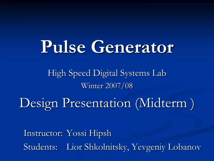
Pulse Generator. High Speed Digital Systems Lab Winter 2007/08 Design Presentation (Midterm ) Instructor: Yossi Hipsh Students: Lior Shkolnitsky, Yevgeniy Lobanov. Topics. Review Block Diagram Bill Of Materials Electrical Scheme Layout Stack Future Plans – Time Table. Review.

E N D
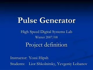
Pulse Generator High Speed Digital Systems Lab Winter 2007/08 Design Presentation (Midterm ) Instructor: Yossi Hipsh Students: Lior Shkolnitsky, Yevgeniy Lobanov
Topics • Review • Block Diagram • Bill Of Materials • Electrical Scheme • Layout Stack • Future Plans – Time Table
Review • The main goal is to build a Programmable Pulse Generator. • The Generator will be integrated into an existing lab experiment, that teaches about High Speed Systems Phenomena: reflections, skew and jitter. • The Generator will create a very short (0.5-1 nsec) and a longer (10-13 nsec) pulse signal into transmission line.
Short pulse Pulse width selection Long pulse Power supply I/O scheme Programmable Pulse Generator
Power Supply 100 nsec 9 V Manual Selector 10 nsec 10 nsec 10 nsec 3.3 V Programmable Delay AND Splitter 5 V Level Translator Oscillator FF TTL DiffLVPECL 0.5-1 nsec Programmable Delay 3.3 V 2.3 V 0.5-1 nsec Detailed Block Diagram Voltage Regulator Voltage Regulator
BOM Appendix 1 (click to jump)
Layout Stack each metal layer - 1oz Copper SIGNAL FR 4 GND FR 4 Vcc (ECL) = 3.3 V each dielectric layer - TBD FR 4 Vtt = 1.3 V FR 4 Vcc (TTL) = 5 V
Questions / Answers Thank you! 10
Appendix 1 Resistors Capacitors Go back… 11
100 nsec 10 nsec 0.5-1 nsec 3.3 V 2.3 V 0.5-1 nsec