Download

1 / 72
730 likes | 996 Views
PROGRAMMING OF 8085 PROCESSOR UNIT II Mr. S. VINOD ASSISTANT PROFESSOR EEE DEPARTMENT. Instruction format and addressing modes Assembly language format - Data transfer, -data manipulation & control instructions Programming: -Loop structure with counting & Indexing

E N D
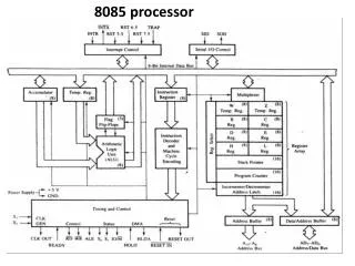
PROGRAMMING OF 8085 PROCESSOR UNIT II Mr. S. VINOD ASSISTANT PROFESSOR EEE DEPARTMENT
Instruction format and addressing modes • Assembly language format - Data transfer, -data manipulation & control instructions • Programming: -Loop structure with counting & Indexing - Look up table - Subroutine instructions stack.
ADDRESSING MODES -Every instruction of a program has to operate on a data. -The method of specifying the data to be operated by the instruction is called Addressing. The 8085 has the following 5 different types of addressing. 1. Immediate Addressing 2. Direct Addressing 3. Register Addressing 4. Register Indirect Addressing 5. Implied Addressing
IMMEDIATE ADDRESSING • In immediate addressing mode, the data is specified in the instruction itself. The data will be a part of the program instruction. • EX. -MVI B, 3EH - Move the data 3EH given in the instruction to B register; -LXI SP, 2700H- Move the data 2700h to stack pointer -ADI 45H- The 8-bit data (operand) is added to the contents of the accumulator and the result is stored in the accumulator -ACI 45H -The 8-bit data (operand) and the Carry flag are added to the contents of the accumulator and the result is stored in the accumulator SUI 45H , SBI 45H , ORI 86H
DIRECT ADDRESSING • In direct addressing mode, the address of the data is specified in the instruction. • The data will be in memory. In this addressing mode, the program instructions and data can be stored in different memory. EX. LDA 1050H - Load the data available in memory location 1050H in to accumulator; SHLD 3000H-The contents of register L are stored into the memory location specified by the 16-bit address in the operand and the contents of H register are stored into the next memory location by incrementing the operand STA 4350H-The contents of the accumulator are copied into the memory location specified by the operand
REGISTER ADDRESSING • In register addressing mode, the instruction specifies the name of the register in which the data is available. EX. MOV A, B - Move the content of B register to A register; SPHL- The instruction loads the contents of the H and L registers into the stack pointer register ADD C-The contents of the operand (register or memory) are added to the contents of the accumulator and the result is stored in the accumulator XCHG-The contents of register H are exchanged with the contents of register D, and the contents of register L are exchanged with the contents of register E
REGISTER INDIRECT ADDRESSING • In register indirect addressing mode, the instruction specifies the name of the register in which the address of the data is available. • Here the data will be in memory and the address will be in the register pair. EX. MOV A, M - The memory data addressed by H L pair is moved to A register. LDAX B -The contents of the designated register pair point to a memory location. This instruction copies the contents of that memory location into the accumulator
IMPLIED ADDRESSING • In implied addressing mode, the instruction itself specifies the data to be operated. EX. CMA - Complement the content of accumulator; RAL-Each binary bit of the accumulator is rotated left by one position through the Carry flag. Bit D7 is placed in the Carry flag, and the Carry flag is placed in the least significant position
1.Calculate the sum of series of numbers. The length of the series is in memory location 4200H and the series begins from memory location 4201H. a. Consider the sum to be 8 bit number. So, ignore carries. Store the sum at memory location 4300H
LDA 4200H MOV C, A : Initialize counter SUB A : sum = 0 LXI H, 420lH : Initialize pointer BACK: ADD M : SUM = SUM + data INX H : increment pointer DCR C : Decrement counter JNZ BACK : if counter 0 repeat STA 4300H : Store sum HLT : Terminate program execution
2.a. To write an assembly language program to multiply two 8-bit numbers. 3.b. To write an assembly language program to division
1.MULTIPLICATION PROGRAM LDA 4200H MOV E, A MVI D, 00H LDA 4201H MOV C, A LXI H,0000H LOOP: DAD D DCR C JNZ LOOP SHLD 4300H HLT program simulation
Division Of Two 8 Bit LDA 2000H ;divisor MOV B,A LDA 2001H ;dividend MVI C, 00H LOOP: CMP B JC BRANCH SUB B INR C JMP LOOP BRANCH: STA 3000H ;reminder MOV A,C STA 3001H ;quotient HLT program simulation
Program START: LXI H, 2000H LXI D, 3000H MVI C, 0AH LOOP: MOV A,M STAX D INX H INX D DCR C JNZ LOOP HLT program simulation
5. PROGRAM FOR SMALLEST NUMBER IN GIVEN ARRAY -Get number of element as first number -compare two number if 1st number is smaller than 2nd then carry will be set so number in acc is small -if reverse move the 2nd number to acc -get the next number repeat the procedure -finally the number in the acc is stored in memory location
lxi h,2000 mov b,m inx h mov a,m dcr b loop: inx h cmp m jc ahead mov a,m ahead: dcr b jnz loop sta 3000 hlt program simulation
6. PROGRAM FOR LARGEST NUMBER IN GIVEN ARRAY -Get number of element as first number -compare two number if 1st number is smaller than 2nd then carry will be set move the 2nd to acc, before jumping check for no carry -or the 1st number will be in acc -get the next number repeat the procedure -finally the number in the acc is stored in memory location
lxi h,2000 mov b,m inx h mov a,m dcr b loop: inx h cmp m jnc ahead mov a,m ahead: dcr b jnz loop sta 3000 hlt
7.SQUARE OF A NUMBER USING LOOKUP TABLE lxi h,2000 //initialize look up table address lda 3000 //get the data cpi 0ah //check the data is > 9 jc AFTER //if yes error mvi a,ffh //error indication sta 3001 jmp STOP AFTER: mov c,a mvi b,00 dad b mov a,m sta 3001 //store the result STOP: hlt
lxi h,2000 mov c,m dcr c REPEAT: mov d,c lxi h,2001 LOOP: mov a,m inx h cmp m jc SKIP mov b,m mov m,a dcx h mov m,b inx h SKIP: dcr d jnz loop dcr c jnz REPEAT hlt
Program 9,10 • Pack the two unpacked BCD number stored in memory locations 2000h and 2001h assume the least significant digit is in stored at 2000h and store the result at 3000h, eg 06 and 07 as 67 • Two digit BCD number is stored in memory location 2000h. Unpacked the bcd number store in 3000h and 3001h such that 3000 will have lower BCD digit
LDA 2000 RLC RLC RLC RLC ANI F0H MOV C, A LDA 2001 ADD C STA 3000 HLT LDA 2000 ANI F0H RRC RRC RRC RRC STA 3000 LDA 2000 ANI 0FH STA 3001 HLT
11. FIND 2'S COMPLEMENT OF 16 BIT NUMBER LDA 2000 CMA ADI 01H STA 3000H LDA 2001 CMA ACI 00H STA 3001H HLT
PROGRAM 12 • Write a program to find the number of negative elements and positive elements in a block of data. Length of the block is in 2000h and data start from 2001h, number of negative element in memory location 3000, and positive element in memory location 3001
LDA 2000H MOV C,A MVI B,00H MVI D,00H LXI H, 2001H BACK: MOV A,M ANI 80H JZ SKIP INR B JMP TOO SKIP: INR D TOO: INX H DCR C JNZ BACK MOV A,B STA 3000H MOV A,D STA 3001H HLT
Program 13.Write a program to count number of 1’s in given data (2000) and store the result in memory location 3000h LDA 2000H MOV D,A MVI B,00 MVI C,08 BACK: RAR JNC SKIP INR B SKIP: DCR C JNZ BACK MOV A,B STA 3000 HLT
Program 14, To find sum of series of even number from the list of numbers LDA 2000H MOV C,A MVI B,00H LXI H,2001H BACK: MOV A,M ANI 01H JNZ SKIP MOV A,B ADD M MOV B,A SKIP: INX H DCR C JNZ BACK STA 3000 HLT
Program 15, program to separate even number from the given list of number and store them in the 3000h and sum in 300F LXI H, 2001H LXI D, 3000H LDA 2000H MOV C,A BACK: MOV A,M ANI 01H JNZ SKIP MOV A,M STAX D INX D SKIP: INX H DCR C JNZ BACK HLT
16. Write A Program To Search The Given Byte In The List Of Data And Store The Address of the in 2001 and 2002 LXI H, 3000H MOV B, M INX H LDA 2000H MOV C,A BACK: MOV A,M CMP C JZ LAST INX H DCR B JNZ BACK LXI H, 0000H SHLD 2001H JMP END LAST: SHLD 2001H END: HLT
17.Write a program for matrix addition LXI H, 2000H LXI B, 2011H LXI C, 3000H BACK: LDAX B ADD M STAX D INX H INX B INX D MOV A, L CPI 0AH JNZ BACK HLT
18.Write a program to generate Fibonacci number LDA 2000H LXI D, 2001 MOV H, A MVI B, 00H MOV A, B STAX D MVI C, 01H MOV A, C INX D STAX D BACK: MOV A,B ADD C INX D STAX D MOV B, C MOV C, A DCR H JNZ BACK HLT
Delays • Each instruction passes through different combinations of Fetch, Memory Read, and Memory Write cycles. • Knowing the combinations of cycles, one can calculate how long such an instruction would require to complete. • B for Number of Bytes • M for Number of Machine Cycles • T for Number of T-State.
Delays • Knowing how many T-States an instruction requires, and keeping in mind that a T-State is one clock cycle long, we can calculate the time using the following formula: Delay = No. of T-States / Frequency • For example a “MVI” instruction uses 7 T-States. Therefore, if the Microprocessor is running at 2 MHz, the instruction would require 3.5 mSeconds to complete.
Delay loops • We can use a loop to produce a certain amount of time delay in a program. • The following is an example of a delay loop: MVI C, FFH 7 T-States LOOP DCR C 4 T-States JNZ LOOP 10 T-States • The first instruction initializes the loop counter and is executed only once requiring only 7 T-States. • The following two instructions form a loop that requires 14 T-States to execute and is repeated 255 times until C becomes 0.
Delay Loops • We need to keep in mind though that in the last iteration of the loop, the JNZ instruction will fail and require only 7 T-States rather than the 10. • Therefore, we must deduct 3 T-States from the total delay to get an accurate delay calculation. • To calculate the delay, we use the following formula: Tdelay = TO + TL • Tdelay = total delay • TO = delay outside the loop • TL = delay of the loop • TO is the sum of all delays outside the loop. • TL is calculated using the formula TL = T X Loop T-States X N10
Delay Loops • Using these formulas, we can calculate the time delay for the previous example: • TO = 7 T-States • Delay of the MVI instruction • TL = (14 X 255) - 3 = 3567 T-States • 14 T-States for the 2 instructions repeated 255 times (FF16 = 25510) reduced by the 3 T-States for the final JNZ. • TDelay = (7 + 3567) X 0.5 mSec = 1.787 mSec • Assuming f = 2 MHz
Using a Register Pair as a Loop Counter • Using a single register, one can repeat a loop for a maximum count of 255 times. • It is possible to increase this count by using a register pair for the loop counter instead of the single register. • A minor problem arises in how to test for the final count since DCX and INX do not modify the flags. • However, if the loop is looking for when the count becomes zero, we can use a small trick by ORing the two registers in the pair and then checking the zero flag.
Using a Register Pair as a Loop Counter • The following is an example of a delay loop set up with a register pair as the loop counter. LXI B, 1000H 10 T-States LOOP DCX B 6 T-States MOV A, C 4 T-States ORA B 4 T-States JNZ LOOP 10 T-States
Using a Register Pair as a Loop Counter • Using the same formula from before, we can calculate: • TO = 10 T-States • The delay for the LXI instruction • TL = (24 X 4096) - 3 = 98301 T- States • 24 T-States for the 4 instructions in the loop repeated 4096 times (100016 = 409610) reduced by the 3 T-States for the JNZ in the last iteration. • TDelay = (10 + 98301) X 0.5 mSec = 49.155 mSec
Is this Final Count? Nested Loops Initialize loop 2 • Nested loops can be easily setup in Assembly language by using two registers for the two loop counters and updating the right register in the right loop. • In the figure, the body of loop2 can be before or after loop1. Body of loop 2 Initialize loop 1 Body of loop 1 Update the count1 No Yes Update the count 2 Is this Final Count? No Yes
Nested Loops for Delay • Instead Register Pairs, a nested loop structure can be used to increase the total delay produced. MVI B, 10H 7 T-States LOOP2 MVI C, FFH 7 T-States LOOP1 DCR C 4 T-States JNZ LOOP1 10 T-States DCR B 4 T-States JNZ LOOP2 10 T-States
Delay Calculation of Nested Loops • The calculation remains the same except that it the formula must be applied recursively to each loop. • Start with the inner loop, then plug that delay in the calculation of the outer loop. • Delay of inner loop • TO1 = 7 T-States • MVI C, FFH instruction • TL1 = (255 X 14) - 3 = 3567 T-States • 14 T-States for the DCR C and JNZ instructions repeated 255 times (FF16 = 25510) minus 3 for the final JNZ. • TLOOP1 = 7 + 3567 = 3574 T-States
Delay Calculation of Nested Loops • Delay of outer loop • TO2 = 7 T-States • MVI B, 10H instruction • TL1 = (16 X (14 + 3574)) - 3 = 57405 T-States • 14 T-States for the DCR B and JNZ instructions and 3574 T-States for loop1 repeated 16 times (1016 = 1610) minus 3 for the final JNZ. • TDelay = 7 + 57405 = 57412 T-States • Total Delay • TDelay = 57412 X 0.5 mSec = 28.706 mSec
Increasing the delay • The delay can be further increased by using register pairs for each of the loop counters in the nested loops setup. • It can also be increased by adding dummy instructions (like NOP) in the body of the loop.
Write a program to generate a delay of 04 sec if the crystal frequency is 5MHz Operating frequency is half of crystal frequency 2.5MHz Time for one T-state = .4 micro sec Number of T-state required = RT/Time for 1 T-state =1000000