Download
1 / 40
410 likes | 529 Views
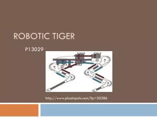
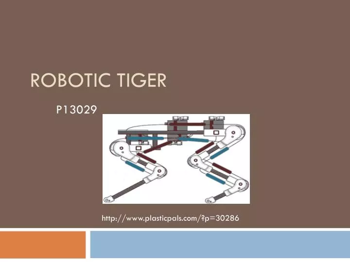
Robotic Tiger. http://www.plasticpals.com/?p=30286 . P13029. Agenda. Project Recap/Proposed Design Updated Engineering Specs Customer Needs System Connections & Interactions McKibben Air Muscle Testing Air Supply Selection Power Supply Selection Logic Selection & Implementation

E N D
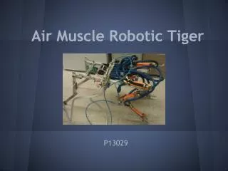
Robotic Tiger http://www.plasticpals.com/?p=30286 P13029
Agenda • Project Recap/Proposed Design • Updated Engineering Specs • Customer Needs • System Connections & Interactions • McKibben Air Muscle Testing • Air Supply Selection • Power Supply Selection • Logic Selection & Implementation • CAD Model • Model Analysis • Bill of Materials • Risk Assessment • Test Plan • MSDII Schedule
Project Recap/Mission Statement • The project goal is to create a robot that mimics a jumping tiger both dynamically and to a lesser extent, aesthetically • The jumping force is to be provided by air muscles
Proposed Design: • Completely self contained robotic tiger • On board air supply, power supply, controls, & muscles • Utilizes McKibben Air Muscles to create jumping motion • Patterned attachment holes in legs to allow for air muscle testing and adjustability • Air release controlled using an ArduinoBoard and sprinkler valves • Rechargeable power & refillable PVC pressure chamber
System Connections Tiger Jumps Forward
Air Muscles • Rubber tube inside of a braided mesh sleeve • Pressurized tube inflates causing the mesh to contract in length • Closely mimics biological muscles
Pressure Chamber Design • Topics of concern • Flow Rate • Currently the muscles fill to slowly to lift the robot from off the ground. • Force during contraction • Currently we are able to achieve a maximum force of about 30lb per air muscle. However the force during the contraction is much lower resulting in slow weak movements. • Bottlenecking • This occurs at all the current joints where air is flowing and is impacted by the smallest inner diameter of the first connection currently this is the solenoid. (shown on the left) Even with larger port sizes (3/8” shown) for fittings the valve inlet and outlet is small (yellow) and restricts flow.
Proposed solution • Design to overcome obstacles • Use high flow rate valves • The current solenoid valves shown on the previous slide do not have good flow rate as demonstrated in the YouTube videos. The solution to this issue is the use of sprinkler valves, they are rated for the pressure required and the offer very high flow rate. This high flow rate will help achieve a faster muscle fill and cause the robot to jump. These will also have to be modified from there original design to allow fast operation.
Proposed Solution • Design to overcome obstacles • Use larger fittings • The current muscle fittings have a small port ID and will need to be increased to allow the muscle to fill at a faster rate.
Proposed solution • Design to overcome obstacles • Change the pressure chamber • Safety??? • The current use of a 3000 psi pressure chamber with 60 psi regulator while good for previous air muscle projects limits the flow rate of the air leaving the chamber. The proposed solution utilizes a lower 20-120 Psi chamber that will allow a greater flow rate leaving the nozzle. Fill location Pressure chamber This Pressure chamber was designed with the use of a very rough calculation to check the final muscle pressure in the muscles was optimal while the pressure in the tank was set to 60Psi. Valve location
Alternative Solution • Design to overcome obstacles • Change the pressure chamber • These aluminum air tanks are lighter but are expensive.
Controls Selection • What we are planning to use: • Arduino Mega 2560 • Simple programming language • 54 channel capability • Fully autonomous • Cost effective (existing part)
Power Supply • 9V battery to power Arduino board • 3 9V batteries in series to power sprinkler valve solenoids • Cheap and lightweight • Solenoids • Draw 400mA for 1 sec to hold valve open, each • At 20 jumps per hour, battery lasts 180 hrs
Solenoid Control Board • Provides signal from the microcontroller to the solenoid valve for muscle actuation. • There will be one iteration of this circuit per solenoid used to control muscle contraction order.
Jump Logic Contract muscle Group 2 Contract muscle Group 3 Contract muscle Group 1 Power On Wait Wait for Go Input Command Yes Release muscles Go? Return No
Testing • Continued air muscle testing was preformed (different way of mounting air muscles tested; hooks on the fitting vs mesh loop used) • Pre-compressing the mesh and stretching the muscles to get a bit more deflection • Wooden leg built for project feasibility testing • Attaching multiple muscles to a leg to get more force • https://www.youtube.com/watch?v=_ObyHcsklsw
Wooden leg Prototype • Problems Encountered and things we Learned: • Need for Tension on muscles for movement to occur • Need for weight on upper body link • Lack of a stop for the upper body link • Unable to launch with stability with only one leg • Leg needs to be angled in order to jump desired way • No way to return to home position yet • Could be improved with faster firing muscles (large orifice size) https://www.youtube.com/watch?v=1i3mJSSaIqI https://www.youtube.com/watch?v=qq48kK5-Li4 https://www.youtube.com/watch?v=5hcW5bUXf6k
Mass Properties • Weight Analysis • Assembly with PVC system 2-tanks ~ 18 lb • PVC system 2-tanks ~ 5 lb • Hind Leg Assembly ~ 1 lb x2 • Front Leg Assembly ~ .8 lb x2 • 80/20 Body ~ 10 lb This picture shows the center of mass as calculated by SolidWorks 2012.
Body Design • Body Design Merits • Strong • Adjustable • Easily test multiple configurations • Light Weight • No Machining
Leg Design • General Design Merits • Adjustable • Muscle anchor points • Hard stops • Pivot points • Simple • Easily Manufactured • Cheap • Versatile • Ability to test and idealize multiple configurations • Light Weight
Leg Design Cont. • Pivot Points • Rod and Shaft Collar Design • Cheap • Proof of concept – prototype • Main Body – Leg Connector • Fork Style Holster • Simple • Proof of concept – prototype • Rod and Shaft Collar
Leg Design Cont. 1 4 5 2 6 3
Hind Leg Design • Function • Extension • Needs to extend with enough force to lift robot off ground • Air muscles in lever configuration • Retraction • Springs • Need to bring legs back but not interfere with extension to extensively This picture is meant to be a visualization of our current idea for muscle ( ) and spring ( ) placement.
Front Leg Design • Uses identical hole pattern as back legs • Allows for adjustability • Hard stops • Spring attachment • Lengths • Initial position
Jump Dynamics • Simulation of take off • Reinforced the need for hard stops on legs • Inputs • Joint moments • Lengths • Masses/CM locations • Initial Angles • Outputs • IC’s for free flight
Jump Dynamics • Future – implement series of event detections • Fix each link when it reaches 45° • Remove the ground constraints at each foot when the normal force is zero
Free Flight Dynamics • Simulation models free flight of tiger • IC’s needed • Angles and rate of change • Position of foot • Uses • Test different setups • Find spring force needed for return
Free Flight Dynamics • Inputs • Spring coefficient • Damping coefficients • Centers of mass • Masses • Lengths • Outputs • Distance traveled • Animation/ positioning • Time for joint return
Free Flight Animation • Future work • Adjust system parameters • Event detection • Receive IC’s from jump program
Test Plan For MSDS II • Further air muscle testing • Looking for faster fill times • Deflection and Force for bigger tube and mesh size • Larger Impulse • Testing with pressure vessel design • Testing full build prototype
Questions? Thank you for your time and feedback