Download
1 / 20
200 likes | 436 Views
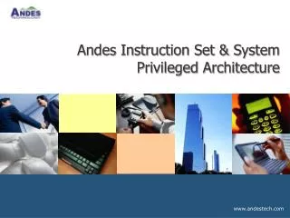
Industrial Automation for Middle Management: DCS Control System Architecture Notes & Course Material II. General Remarks. Function: Control, monitor and supervise all the detector components and the infrastructure of the experiment; No physics data. Features:

E N D
Industrial Automation for Middle Management: DCS Control System Architecture Notes & Course Material II
General Remarks • Function: Control, monitor and supervise all the detector • components and the infrastructure of the experiment; • No physics data. • Features: • Natural integration with other systems (Safety, BeamLine,etc.) • A supervisory control hierarchy of loosely coupled sub-systems • it includes all levels: from the hardware to the interaction with the operator
Detector Control System (DCS) • Control various MINOS HV, LV, B-field, Relay, • Relay Rack Protection, and Temperature, …. • Acquire Beam/Accelerator line data. • Read back the HV/LV/Temp,… values, display them graphically or in tables, and monitor them. • Set alarms upon unacceptable conditions. • Record the readback values, store them on the system online DB for future access by user.
Questions for the DCS System • Hardware configuration. • Software configuration; What type of SCADA? • Beam line data interface. • Data-Base interface. • DAQ DCS communication. • Type of systems to be monitored/controlled. • Number of monitored/controlled channels.
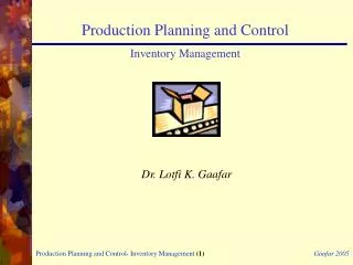
Standard DCS Model OPI Operator Interface OPI Operator Interface LAN-ETHERNET IOC Input/Output Cntrl IOC Input/Output Cntrl OPI: Operator Interface IOC: Input/Output Controller DCS: Detector Control System
Control and Data Flow Database RC Run Control Calibration System DCS Detector Control System Experimental Area and Accelerator DAQ/Trigger Experimental MINOS Devices Experimental Control DAQ Data Flow Control Data Flow DCS Data Flow
Magnetic Field Monitor GPIB DTM LAN-ETHERNET IEEE-488 GPIB-ENET IOC OPI Detector System OPI: Operator Interface IOC: Input/Output Controller
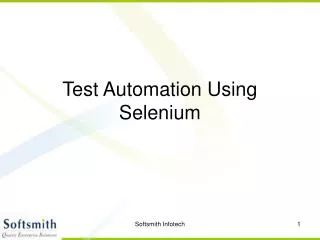
DCS Architecture (physical subsystem layout) Remote Workstations OPI OPI terminal OPI terminal laptop Oracle DB WAN SCADA FNAL Safety Server DB server OPI Local Workstations OPI terminal bridge bridge LAN-ETHERNET I/O Servers distributed in Experimental area OPC IOS IOS IOS GPIB-ENET Beam Server PLC GPIB RS232 GPS RS232 LeCroy 1440 MIL/STD-1553B fieldbus CAN fieldbus Analog/Digital channels, PLC, Fieldbuses PLC fieldbuses Beam-line Experiment Sub-Detectors & Swics,BPM Experimental Equipment Magnets, Scalers
MIL-STD-1553B System Configuration LAN MIL-STD-1553B LAN MIL-STD-1553B 1553 Controller Control Status Tripper Circuit AC BREAKER D0 Relay Rack Monitor Firus Alert Relay Output External Fault Inputs Interface Chassis Blower Interlock Output Water Interlock Output Airflow Sensor Drip Sensor Humidity Sensor Smoke Sensor Waterflow Sensor
PMT LeCroy HV Monitor Detector System LAN-ETHERNET RS232 OPI RS232 to RS485 LeCroy 1440 LeCroy 1440 LeCroy 1445 LeCroy 1443 LeCroy 1445 LeCroy 1443 IOC HV to PMT HV to PMT OPI: Operator Interface IOC: Input/Output Controller
Front End/HUB Monitor LAN-ETHERNET CAN Fieldbus OPI PCI-CAN Front End HUB Front End HUB A/D Module A/D Module IOC OPI: Operator Interface IOC: Input/Output Controller
A SCADA for industrial Automation User Process Utilities C,C++,VBA Wizards SCADA Engine Process Alarm handling Event/Alarm logging Historical trending Networking Device Servers
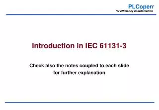
DCS Functional Subsystem Layout RC Run Control DAQ/Trigger FE Controllers (download constants) SCADA System Database Ethernet Beam Line Interface Slow Control Real Time Database HV/LV Magnet Relay Racks FE/BE crates Environment... RTDB CAN Fieldbus RS232 GPIB Ethernet
Supervisory Control and Data Acquisition (SCADA) • Commercial systems, typically used in • industrial production plants. • Examples such as: • LabVIEW/BridgeVIEW from NI • FIX from Intellution • EPICS, etc. • Work to do after the choice of the SCADA • Adding our functionality • Interface to DAQ
DAQ & DCS • Operationally independent • Different architecture and technologies • Linked for information exchange signals and messages • Possible big overlap of software development tools GUIs, other application • DCS interfaces to DAQ services (DB) • DCS provides information to DAQ about • “external systems”
CAN FIELDBUS The Controller Area Network: • Is a high-integrity serial data communication bus for real-time appl. • Operates at data rates of up to 1Mb/sec • Has excellent error detection • Was originally designed for the automotive companies • It is now being used in many other industrial automation and • control applications • It has been recommended as a CERN standard by the Working Group on Fieldbuses together with PROFIBUS and WORLDFIP
MIL-STD-1553 FIELDBUS • Is the standard for data communication over twisted pair cabling • on board military platforms. • Operates at 1MHz clock. • Bus lengths >100meters. • High noise rejection/Very robust. • FNAL/D0 uses it for Relay Rack monitor • 1U rack profile • 64 A/D channels • 8 D/A channels • 4 Binary channels
Type of Subsystems (1) 1) Steel plates Thermal sensors Interlocks 2) Magnet a) Hall probes b) Magnet coil a) Coil power supplies b) Coil Cooling system Thermal sensors electrical sensors Interlocks 3) Scintillator detector a) HV monitor/control b) PMT integrated current monitor 4) Electronics a) Front end units b) Hubs and interface crates c) GPS control and Spill monitoring 5) Relay Rack safety monitoring
Type of Subsystems (2) 6) Environmental conditions a) temperature, humidity, dew point, ventilation 7) Various scalers to monitor the rates of the detector 8) Beam-line monitor (Swics, BPM, rates, etc.) 9) Miscellaneous a) Disk/Memory usage
FIX-Dynamics • Fix-Dynamics is a version of the PC program FIX (for Fully • Integrated Control System) by Intellution. • This is an “Industrial Automation Software System” which allows • a PC to control and monitor equipment, in industrial and other • setting. CDF-FNAL uses this system for RunII. • Features of Fix-Dynamics: • Full color graphics capability for graphs, controls, etc. • User defined alarms setup (with multiple levels of limits in DB). • Extensive internet support. • Supports various hardware: PLC, RS232, GPIB, …. • Avoids extensive programming effort. • Don’t need several full time people to support the DCS. • Easy learning curve. • Provides interface for creating user pages, trend plots, etc.

![Computer Architecture & Operating System [O.S.]](https://cdn0.slideserve.com/35278/computer-architecture-operating-system-o-s-dt.jpg)