Download
1 / 21
210 likes | 225 Views
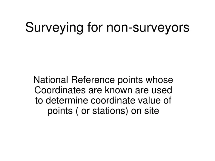
Surveying for non-surveyors. National Reference points whose Coordinates are known are used to determine coordinate value of points ( or stations) on site. National Reference points connected to site stations by angular and distance measurement. Site station 1. National Reference point.

E N D
Surveying for non-surveyors National Reference points whose Coordinates are known are used to determine coordinate value of points ( or stations) on site
National Reference points connected to site stations by angular and distance measurement Site station 1 National Reference point Site station 2
Site station 1 National Reference point Northings Eastings Site station 2 The Coordinates of the site stations are determined from the angular and distance measurements
The survey measurement can never be without errors • So we do calculations to distribute the errors evenly around all our measurements • In the hope that this will mean smaller errors on any particular set of coordinates.
Angles and distances are measured with an instrument called a Total Station • This may be thought of as a particularly expensive protractor! • The angles can be measured to the 5th decimal place of accuracy. • The angles in this country are measured in Degrees, Minutes and seconds. • Distances are measured electromagnetically (i.e. by light reflection)
Consider the angular measurement 360 degrees = 1 complete circle 1 Degree = 60 Minutes 1Minute = 60 Seconds Also remember that angles can also be measured by the arc length to radius ratio………i.e. Radians ( л radians = 180 degree)
To reduce errors angles are measured twice at each station • These are known as Face 1 and Face 2 readings---- the average value is used • ( = the mean included angle) • The readings are simply the values pointed to on the protractor and we need to subtract one reading from another to determine the angle.
Example First reading = 35° Second reading =165° Angle turned through = 165 ° – 35 ° = 130 °
Do not be fooled by these readings! First reading = 335° Second reading =85° Angle turned through = 85 ° – 335 ° = 110 ° Note: when the readings pass through 360° the subtraction becomes thus: 335° to 360 ° = 25 ° PLUS 0 ° to 85 ° = 85 ° Total angle turned through = 25 ° + 85 ° = 110 °
The survey usually closes on itself for greater accuracy • Hence we can check that the sum of the internal angles are correct • And distribute around the survey any errors present.
Correcting Angular Errors • ΣInternal angles of polygon = (2N-4)90° • Dist. Coeff. = closing error / N • Corrected angle = Measured angle – Dist. Coeff. • Where closing error = Theorectical sum – actual sum of internal angles • N = Number of sides or angles in polygon
Distance are often also measured several times • Again the average value is used to help determine the coordinates of the site stations.
Trigonometry • A recap of your knowledge of trigonometry may be useful here. • Refer to Trig. File • This knowledge will be used to determine the North and East vectors for the distance between stations • These are known are North and East Partials.
Partials East Partial = L x Cos( Θ) Θ North Partial = L x Sin (Θ) L Northings Eastings
Whole Circle Bearings • The angle used in the Partial calculations is the angle between the line from station to station and the North or East axis. • A more general solutions is to use the Whole Circle Bearing (WCB) of the line. • A WCB is the angle a line makes with the North Measured in clockwise direction. • Only the WCB of the first line is determined on site. The rest are calculated from the known relationship between adjacent lines.
Partials from WCB value WCB East Partial = L x Sin( WCB) L North Partial = L x Cos (WCB) Northings Eastings NB sin & cos different to previous
Coordinates • The coordinates of stations are then calculated from adjacent stations, starting with the first known reference point. Pe N1 Pn N2 = N1- Pn E1 E2 = E1 + Pe
Site Measurement errors • Of course the coordinates we end up with have errors and if we do a closed survey ( returning to the starting point) we will notice that the coordinates for the end point ( which is in fact the starting point) do not match the starting point values – the closing error. • We do a correction called the Bowditch correction to compensate for this.
Closing errors N1 en N1’ Closing error ee E1’ E1
Bowditch Correction • This suggests that the greater the length of a measured line the greater the error in measurement is present. • The amount of correction to a line therefore depends on it’s length. The longer the line the more correction is needed.
Formula in Bowditch Correction • The closing error in the North and East directions are found first by summing all the partials. • Correction to Partials: = (Line length / Σ line lengths) x closing error in east or north direction • i.e. a fraction x closing error • the partials are corrected in accordance with this premise. • The corrected coordinates are then computed.