Download
1 / 48
610 likes | 973 Views
BIOS. Chapter 7. Overview. In this chapter, you will learn how to Explain the function of BIOS Distinguish among various CMOS setup utility options Describe option ROM and device drivers. We need to talk…. Necessary CPU Functions. Two functions are necessary for devices to work:

E N D
BIOS Chapter 7
Overview In this chapter, you will learn how to Explain the function of BIOS Distinguish among various CMOS setup utility options Describe option ROM and device drivers
Necessary CPU Functions • Two functions are necessary for devices to work: • The CPU must have a way to talk to devices. • Devices must have a way to send data to and receive data from the CPU. • Fix: We’ll elevate the MCC into the chipset and use that to connect the CPU to all the devices.
The Northbridge and Southbridge • The Northbridge is the first chip in the chipset. • Connects the CPU to video and/or memory • The Southbridge, the second in the chipset • handles all inputs and outputs to the many devices in the PC and extends data bus and address bus to all other parts of PC. • The chipset extends the data bus to touch all the devices. • It also extends the address bus.
The Northbridge and Southbridge (continued) Figure 1: Meet the Northbridge
The Northbridge and Southbridge (continued) Figure 2: The chipset extending the data bus
The Northbridge and Southbridge (continued) Figure 3: Every device in your computer connects to the address bus.
Talking to the Keyboard • Example: how the CPU recognizes when a key is pressed • A keyboard controller chip (now part of the Southbridge) recognizes when a key is pressed. Let’s say the “J” key was pressed. • The keyboard controller scans the matrix of wires on the keyboard and puts the scan code for the “J” key into its register. • The keyboard controller then gets the attention of the CPU, essentially saying, “I have some data.” • When the CPU addresses the keyboard controller, the keyboard controller places the data onto the external data bus so that the CPU can read it.
Talking to the Keyboard (continued) • Example: how the CPU recognizes when a key is pressed (continued) • For all of this to work, programming has to be readily available to the CPU, and the CPU needs this programming as soon as it is powered up—this programming is stored in ROM. Figure 4: A keyboard chip on a Pentium motherboard Figure 5: Electronic view of the keyboard controller
Talking to the Keyboard (continued) Figure 6: Scan code stored in keyboard controller’s register
Talking to the Keyboard (continued) Figure 7: The CPU ponders the age-old dilemma of how to get the 8042 to cough up its data.
BIOS (Basic Input/Output Services) • The read-only memory (ROM) chip also called system ROM or the ROM BIOS • Nonvolatile (does not lose its programming, even if no power) • Read-only means it cannot be easily erased • Stores hundreds of programs called services; collectively, this is the basic input/output services or system (BIOS) • System ROM typically holds 64KB (65,536) lines of data code, though current Flash ROM is often 2 MB or more in size • Historically, a DIPP chip with a shiny label on it, but it has gone through many changes
BIOS (continued) • Each time the CPU needs to talk to a component, it refers to the BIOS for the program to talk to that specific device. • The CPU talks to the ROM BIOS the same way it talks to RAM—through the address bus—with some of the address bus being reserved for the ROM BIOS. • Many devices and expansion cards have their communication programs on ROM chips.
BIOS (continued) Figure 8: Typical flash ROM
BIOS (continued) Figure 9: Function of the flash ROM chip
BIOS (continued) Figure 10: CPU running BIOS service
Complementary Metal-Oxide Semiconductor (CMOS) • What it is: • A separate chip from the ROM BIOS, though most often now part of the Southbridge • Volatile: kept alive by a battery • Also acts as a clock and keeps the date and time • Stores only the changeable data, not programs, read by the BIOS • Customizable via setup program. The setup program is stored on the ROM BIOS, but the customizable settings are on the CMOS chip. • Stores semipermanent, user-changeable data related to hardware components such as disk drives, RAM, and I/O ports
Complementary Metal-Oxide Semiconductor (CMOS) (continued) • What it is (continued): • Is typically 64 KB, but only a fraction of that is actually used to store the critical data Figure 11: Old-style CMOS
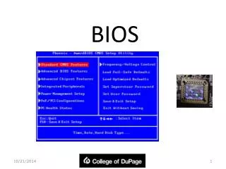
Modify CMOS: The Setup Program • PCs come with CMOS setup programs • Allows you to access and modify CMOS data • The CMOS setup program is built into the system ROM chip and may be accessed in a number of ways, depending on the manufacturer and date of the ROM chip. • There are many BIOS manufacturers—each manufacturer uses a different key sequence to enter the CMOS setup and may use a different key sequence within different models of the same brand
Modify CMOS: The Setup Program (continued) Figure 13: Award/Phoenix BIOS information Figure 12: AMI BIOS information
Modify CMOS: The Setup Program (continued) • The most common BIOS manufacturers and some common key sequences to enter the CMOS Setup (usually says on the boot screen) are: • Award (most common): Press DEL • Phoenix: Press CTRL-ALT-ESC or F2 • American Megatrends (AMI): Press DEL • For others press F1, CTRL-ALT-INS, CTRL-ALT-ENTER, or CTRL-ALT-S
Modify CMOS: The Setup Program (continued) Figure 15: Standard CMOS Features screen Figure 14: Typical CMOS main screen by Award
Modify CMOS: The Setup Program (continued) Figure 17: Older Award setup screen Figure 16: Phoenix BIOS CMOS setup utility Main screen
Modify CMOS: The Setup Program (continued) • MB Intelligent Tweaker (M.I.T.): • You can use the MB Intelligent Tweaker (M.I.T.) to change the voltage and multiplier settings on the motherboard for the CPU from the defaults. • Motherboards that cater to overclockers tend to have this option. • Normally, you would keep these settings at AUTO or default.
Modify CMOS: The Setup Program (continued) Figure 18: MB Intelligent Tweaker (M.I.T.)
Modify CMOS: The Setup Program (continued) • Advanced BIOS Features: Boot option, as well as other miscellaneous items usually found here • Virtualization Support: A virtual machine is a powerful type of program that enables you to run multiple software-based machines inside your physical PC • Recreates (or virtualizes) the motherboard, hard drives, RAM, network adapters, and more, and is just as powerful as a real PC • To run these virtual machines, you need a very powerful PC—CPU manufacturers have added hardware-assisted virtualization
Modify CMOS: The Setup Program (continued) Figure 19: Advanced BIOS Features
Modify CMOS: The Setup Program (continued) • Advanced BIOS Features (continued): • Chassis Intrusion Detection: When enabled, it is used to warn an administrator if someone has opened the case. Often a hardware switch and a BIOS setting are used to detect an intrusion • Advanced chipset features: Deals with low-level chipset functions • Normally, you would leave settings here at their default values • Integrated peripherals: Used to configure ports
Modify CMOS: The Setup Program (continued) Figure 20: Advanced Chipset Features
Modify CMOS: The Setup Program (continued) Figure 21: Integrated Peripherals
Modify CMOS: The Setup Program (continued) • Power management setup: • Used to set the sleep timers method. Also often used to configure IRQs (Enabled/Disabled/AUTO) • Overclocking: • Many PCs have CMOS setup menus that display information about the CPU, RAM, and GPU and include controls for overclocking them • PnP/PCI configuration: • Set up plug-and-play configurations and also sometimes IRQ settings
Modify CMOS: The Setup Program (continued) Figure 23: PnP/PCI Configurations Figure 22: Power Management Setup
Modify CMOS: The Setup Program (continued) • And the rest of the CMOS settings: • PC Health Status: Often display information about voltage, CPU and case temperatures, and fan speed • Load Fail-Safe: These options reset all settings to their fail-safe or factory default settings. Generally used when a setting prevents a system from booting or to fix corrupt settings • Optimized: Sets CMOS settings for the best possible speed/stability • Set Password: Set user password (a password to boot the computer) or an administrator password (to get into CMOS)
Modify CMOS: The Setup Program (continued) Figure 24: CMOS password prompt
Modify CMOS: The Setup Program (continued) • And the rest of the CMOS settings (continued): • DriveLock passwords: Enables an ATA security feature that prevents unauthorized access to a hard drive. A password is required to boot. • Some PC manufacturers also include LoJack security features in their BIOS—this way, if your PC is stolen, you can track its location, install a key logger, or even remotely shut down your computer.
Modify CMOS: The Setup Program (continued) • And the rest of the CMOS settings (continued): • Trusted Platform Module (TPM): Acts as a cryptoprocessor for various encryption technologies such as Digital Rights Management (DRM), disk encryption, network access control, application execution control, and password protection • Exiting and saving settings: Saves or doesn’t save the changes made to the CMOS
Option ROM and Device Drivers • Option ROM or Bring your own BIOS (BYOB) • Individual ROM BIOS on expansion cards and devices • Device drivers loaded into RAM at boot • Device drivers—each a file stored on the hard drive that loads all the BIOS commands for a specific device into RAM at boot • Comes with a device you buy as an installation disc (floppy or CD-ROM)
Option ROM and Device Drivers (continued) Figure 25: Option ROM
Option ROM and Device Drivers (continued) Figure 27: Windows asking for the installation disc Figure 26: Option ROM at boot
Option ROM and Device Drivers (continued) • BIOS, BIOS, everywhere • Every piece of hardware must have a program that allows the CPU to communicate with it • The program may be on motherboard ROM • The program may be on ROM on the individual hardware • The program may be on a driver
UEFI • BIOS hasn’t changed much since it was conceived back in the 1980s. • BIOS works only in 16-bit mode and depends on x86-compliant hardware. • In addition, if there is more than one operating system loaded on a single drive, you need one of those installed OSes to act as a boot loader. • In 2005, Intel released its Extensible Firmware Interface (EFI) for public standards, creating the Unified EFI forum to manage the specification. • Became the Unified Extensible Firmware Interface (UEFI)
UEFI (continued) • UEFI acts as a super-BIOS, doing the same job in a 64-bit environment. • UEFI: • Supports 32-bit or 64-bit booting • Handles all boot-loading duties • Is not dependent on x86 firmware • UEFI motherboards only became available in 2011 due to limitations of older BIOS to handle larger MBR partition support (>2.2 TB) • 3 TB drives had issues with older BIOS
UEFI (continued) • UEFI motherboards support booting a newer type of hard drive partitioning called GUID Partition Table (GPT) • Supports partitions larger than 2.2 TB
UEFI (continued) Figure 28: Here’s what happens when you install Windows 7 on a greater-than-2.2-TB drive using regular BIOS.
UEFI (continued) Figure 29: Here’s what happens when you install Windows 7 on a greater-than-2.2-TB drive using UEFI.
UEFI (continued) Figure 31: POST and system setup are still here. Figure 30: ASUS EFI BIOS Utility