Download
1 / 66
660 likes | 662 Views
Bilan Workshop SLHC Inner detector replacement. Equipe Jacky Ballansat,Pierre Delebecque,Nicolas Massol,Thibaut Rambure,Isabelle Wingerter.

E N D
Bilan Workshop SLHC Inner detector replacement Equipe Jacky Ballansat,Pierre Delebecque,Nicolas Massol,Thibaut Rambure,Isabelle Wingerter
0 - Introduction1 – Impressions générales du workshop 2 – Les raisons de l’upgrade 3 – B_layer replacement4 - Les objectifs de SLHC5 – Les working groups6 - Schedules7 – Les voies de développement8 – L’organisation
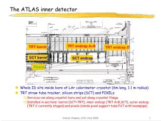
0 - Introduction • Présentation détecteur actuel • Equipe et collaboration : unité ATLAS ID upgrade France : CPPM-LAPP-LPNHE • Correspondant Physique ?
0 - Introduction Strawman
1 - Impressions générales du workshop B-layer remplacement(- temps, - CHF, - personnes, ++++ difficultés intervention, ? Intérêt physique?) Techniquement difficile à mettre en œuvre (installation) Problème de délai pour avoir une solution Shutdown nécessaire risque de pénaliser l’utilisation de la machine (au moins 10 mois)SLHCBeaucoup de travail déjà effectué en mécanique Etudes très intéressantes Délais annoncés hyper serrés (baseline consolidée d’ici printemps 2008) Période de shutdown décalée de 1 an entre ATLAS et CMS Choix des solutions et planification difficile tant que LHC n’a pas démarré !!! Equipes occupées avec détecteur actuel Equipe ingénierie managée par Andréa Catinaccio : bien organisée
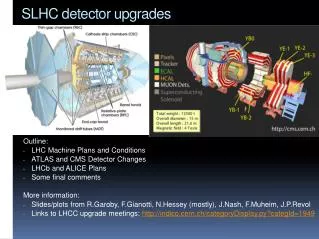
2 - Les raisons de l’upgrade • LHC needs to do a major replacement of interaction region quadrupoles after an integrated luminosity of ~700 fb-1. When it will happen has still a large incertitude (LHC has still to startup and has >1 year delay to 2003 plot). • This would happen ~2015. SLHC upgrade has today scheduled an upgrade of ATLAS for 2015÷2016 shutdown. • B-Layer : dégradation des sensors et de l’électronique sur quelques années de fonctionnements. Grande incertitude à confirmer quand la machine fonctionnera. La durée de vie sera t-elle aussi courte que prévue ? Est-ce que cela vaut le coup par rapport à la difficulté des modifications à mettre en oeuvre ? • Température de fonctionnement plus grande que prévue (0°C au lieu de -7°C end of life time) : couplage thermique tube/oméga modifié, problèmes de pression • Fuites des tubes de refroidissement • Défaillance des “optoboards” des modules
Module temperature [cont.ed] T1= +1 C T2= +10 C Layer 2 [R=122.5mm] 50% of the staves TMAX= +10 C 50% of the staves TMAX= +1 C Layer 1 and B-Layer [R=88.5 ; 50.5mm] 100% of the staves TMAX= +1 C 2 - Les raisons de l’upgrade : problèmes thermiques D. Giugni Upgrade Workshop - Valencia Dec 2007- 7
3 – B-layer replacement : les grandes options • Replacing the current B-layer with a similar layer (current baseline) • Adding a new layer inside the current system • Replacing the entire PIXEL system with a new system as ambitious as possible • Keeping several options open but defining a plan (in time and identifying key issues) that can guide us towards a decision in the coming years. • Permutations/derivations/ developments of the above.
3 – B-layer replacement : les scénarios “Replacement” “Insertable” A B
3 – B-layer replacement : les problématiques • Intérêt pour la physique : choix solution, définition nouvelle couche => meilleures performances (présentation sacha simulation sur différentes options) • Faisabilité technique ( nouvelles structures, nouveaux composants, services, insertion,…) • Problème du rayonnement rémanent • Ouverture des services : long et délicat • Voies d’amélioration : réduction de matière (++) réduction de rayon • Problème de la dégradation des sensors “chauds” durant la période d’intervention
3 – B-layer replacement : évaluation • Commité ATLAS nommé pour évaluer le dossier dans les 6 mois
Is it a desperate picture? Yes, it is. So many issues to solve: Cutting inside-out an activated Be Beam Pipe in the pit is definitely very challenging (radioactive and toxic). Difficult to avoid contamination of the detector and damages to the layers that should keep working. Disk and L1 modules are few cm away. All the work is done at PP1 in a very activated environmental. The situation seems to be much worse than on the surface. Feeding the support wires from PP1 A-side to the C-side (and vice versa) without damaging the detector also seems very tricky. Cooling services should be on the A-side and pass at PP1 through ~17mm gap around the beam pipe . Cannot use the extra cooling of the disk sector because the capillary is not accessible . During the bakeout the pipe should get hot and degrade the thermal performance of the cooling right when it is used to protect the BLayer. Clearly we cannot remove the old BLayer in the pit… it does not pass through the clearance at PP1. The advantage of a layer with a smaller radius is significantly mitigated by the dead mass of the actual B-layer. The New BLayer will have poor stability performances. The stability budget for the actual BLayer is 50, 17 and 100mm respectively on R, F and Z. This requirement won’t be fulfilled with a layer supported off the Beam Pipe. As said, this is not a proposal. A scenario has been depicted to outline the numerous complications and issues that have to be addressed even before start thinking seriously to insert a new layer without taking the pixel package to the surface. 3 – B-layer replacement : état d’esprit 12
LHC vs time: a wild guess … L=1035 4 – Les objectifs de SLHC
Engineering and WG’s 5 – Les working groups • The engineering organization is under discussion with David and Marzio. • WG’s created to build up expertise in specific areas: • Engineering / Integration WG (Engineering Layout, Structures, Services & PP, Interfaces, Installation …) • In progress: Services WG (analysis and impact of existing Atlas Services on detector design) • The different WG’s involve some common names • Members already heavily involved in the current ID installation.
WG on Engineering / Integration 5 – Les working groups Participating people: now covering: _____________________________________________________________ Anatoli Gordeev Structures Susan Duffin Layout, Assembly, Installation, Tatiana Klioutchnikova Installation, Services (Claude Menot) Eric Perrin Inner Barrel Layout Gerard Barbier Inner Barrel Layout Patrick Werneke EC layout Eric Anderssen; Pixel Danilo Giugni; Pixel Neal David Hartman; Pixel Justin Richard Greenhalgh Schedule, Specifications Andy Nichols Inner Services Jason Tarrant Inner Services Georg Viehhauser Cooling, connectivity, TE. Christophe Bault (Integration) Siegfried Wenig Services Andrea Catinaccio Integration R. Vuillermet Integration (TBC) & others joining: non exhaustive list!
WG on Services 5 – Les working groups • Participating people (TBC) • _______________________________________________________ • - Siegfried Wenig • Sergei Maliukov • Hans Danielsson • Georg Viehhauser • A. Catinaccio • Tatiana Klioutchnikova • - Nicolas Massol (TBC) • other engineers, designers and technicians are needed • Input and feedback from Cooling, Powering and Readout groups
5 – Les working groups : management - organisation • Equipe d’ingénierie centralisée pour l’intégration • Conceptual design global intégré • Analyse des avantages et inconvénients des différentes options • Distribution des études particulières • Mise en place rapide pour conceptual design mi-2008
Schedule design 6 – Schedules
Schedule installation 6 – Schedules
7 – Les voies de développement : points critiques • Installation – interfaces • Services • Problèmes thermiques/refroidissement • Transparence • Stabilité dimensionnelle • Activation des zones d’intervention et des composants • Coûts • Délais • Fabrication réaliste
7 – Les voies de développement : spécifications Design Considerations • Provide support for staves with assumed requirements… • 1. vibrational stability < 10 mm (for track reconstruction) • 2. stave to stave placement ~ 300 mm R-f (for hermiticity • 3. stave sag < 100 mm (simplicity of sensor-sensor alignment) • Allow for realistic assembly sequence • Consider details of services including weight and installation • Manufacturability • Provide large structural safety margins Focus has been on barrel support, but weight, services and volume of encaps are considered/estimated
7 – Les voies de développement : installation • Etude pour extraire l’ancien détecteur et mettre le nouveau : influence très sensiblement le nouveau design du détecteur • Compromis intégration surface/puit : détecteur en une seule longueur ou plusieurs parties • Services : influence notable sur design / interfaces avec groupes utilisateurs des services. Modification des services actuels difficilement envisageable.
7 – Les voies de développement : installation Existing Services – Pixel
7 – Les voies de développement : Etudes pixels barrel – questions générales • Question modularité détecteur : 1, 2 ou 3 parties en fonction des contraintes d’installation • Comment se passer au maximum des éléments de structure pour gagner de la matière ?
7 – Les voies de développement : Etudes pixels barrel – propositions Proposition de Gérard Barbier (Uni-GE)
7 – Les voies de développement : Etudes pixels barrel – propositions This pre-study by Gerard Barbier (Uni-GE): Common cylinder for the two innermost short strip layers Common cylinder for 1 short strip and 1 long strip layer Outermost long strip layer mounted inside ext cylinder Outside surface for thermal enclosure? Space to develop a three point mounting? Cylinder machining only on the outside.
7 – Les voies de développement : Etude thermiques - propositions Propositions de M. Cepeda, S. Dardin, M. Gilchriese, C. Haber and R. Post (LBNL) W. Miller and W. Miller, Jr (iTi)
7 – Les voies de développement : Etudes pixels barrel – propositions • Shell Concept • Potentially supports two stave layers • Locating features in mounting rings are machined in one set-up • Rings are inserted over shell and held in place with alignment fixture during bonding to shell • 1m Stave Assembly • Stave mounts from end, engaging alignment pins in rings • Staves meet at center, locked at this point Locating pins in rings Light weight composite sandwich rings
7 – Les voies de développement : Etudes pixels barrel – propositions Prototype Construction POCO foam: about 0.5 g/cc thermally conducting carbon foam 4.9 mm tube/foam 2.8mm tube/foam Carbon honeycomb Facings are K13D2U fiber laminates All tubes aluminum Flattened tube 1m prototype Note prototype width is about 7cm – set in 2006
Quarter model 895560 fluid elements 584136 solid elements 96069 adhesive elements Thermal solution With air and wire bonds Similar results to half size model 7 – Les voies de développement : Etudes pixels barrel – propositions Bridge Model-1/4 Size with Air and Wire Bonds Detector peak temperature -23.1C
7 – Les voies de développement : Etude thermiques - propositions Propositions de M. Gilchriese, M. Garcia-Sciveres, M. Cepeda(LBNL) W. Miller and W. Miller, Jr (iTi)
7 – Les voies de développement : Etudes pixels barrel – propositions Proposition 1 Mousse de carbone Tube aluminium Fines peau composite carbone
7 – Les voies de développement : Etudes pixels barrel – propositions Proposition 2 alternative à la précédente Modules
7 – Les voies de développement : Etudes pixels barrel – propositions Proposition 3 Tube externe Mousse de carbone Tube aluminium
7 – Les voies de développement : Etudes pixels barrel – propositions Proposition 4 alternative à la précédente Tube externe Mousse de carbone Tube aluminium Tube inséré dans la mousse
Carbon foams with good thermal conductivity, but significant density, are available from multiple producers POCO foam: eg. = 0.55 g/cc and K(out) 135 and K(in) 45 K-foam: eg. = 0.34 g/cc and K(out) 55 and K(in) ? We have, in fact, made staves with POCO foam/round tube as part of upgrade R&D for outer silicon tracker. We have now worked with company to make samples with about 0.15 g/cc and K of about 45(isotropic). In future, are hoping to also investigate carbon nanotube(CNT) loaded materials with same company and perhaps CNT “cloth” under development for heat spreaders for ICs. CNT have very high K along tube direction >1000. 7 – Les voies de développement : Etudes pixels barrel – propositions Development Work
IR camera used Water coolant at 1.0 l/min at 20C. Vary power level in silicon heater And separately in copper-kapton heaters to about match Power/Area 7 – Les voies de développement : Etudes pixels barrel – propositions Thermal Performance T in boxes
Integrated monolithic concept appears to be structurally and thermally feasible Multiple stave concepts developed and also feasible (no surprise) All based on edge-to-edge modules (no shingling). Low-density, thermally conductive foam with very thin carbon-fiber facings appears to be feasible approach mechanically and thermally. First prototypes made and validation in progress. 7 – Les voies de développement : Etudes pixels barrel – propositions Conclusion
7 – Les voies de développement : Etudes pixels barrel – propositions Proposition de S. Duffin, A. Gordeev, D. Lynn, G. Mahler, Y. Semertzidis (BrookhavenNL)
7 – Les voies de développement : Etudes pixels barrel – propositions Inner Detector Mechanical Support Studies S. Duffin, A. Gordeev, D. Lynn, G. Mahler, Y. Semertzidis--BNL Atlas Tracker Upgrade Workshop, Valencia, Spain, Dec 12-14, 2007
7 – Les voies de développement : Etudes pixels barrel – propositions Structural Simulations • Structural response of long strip and short strip cylinders to 1000 kg distributed load • Cylinders modeled in solid aluminum with moment of inertia equivalent to composite with ½ mm skins and 12.7 mm thick honeycomb (corresponding to 0.45% radiation length per cylinder if manufactured in carbon fiber) Deformation Shear Stresses Max = 80 mm • Max equiv stress = 16 MPa at ear attachment point (also location of max shear stress in structure), 1st Harmonic at 53 Hz • Max shear stress on barrel occurs at attachment of barrel to flange; shear stress = 0.13 MPa (typical medium density honeycomb shear strength ~ 1MPa) • Good structural safety margins (but need refined weight estimates)
7 – Les voies de développement : Etudes pixels barrel – propositions Mechanical Support Concepts That Have Been Considered Open Space Frame (Fall 06) Closed Space Frame (Winter 07) Both approaches assumed: - Stiff staves with cantilevered support to minimize stave sag - 3 separate frames: one for pixels, one for long . strips, one for short strips - Flanges serve to mount multiple stave layers - Frames installed and interconnected via internal rails Both space frame approaches led to concerns about the sensitivity of stave bending and potential damage due to applied forces in z-direction (e.g. during installation). Therefore we have been considering… Cylinders (Spring 07 to present)
7 – Les voies de développement : Etudes pixels barrel – propositions Current Cylinder Support Baseline Long Strip Cylinders (4 meter length) Long Strip Flanges Rail Attachment “Ear” Short Strip Flanges Short Strip Cylinders (2 meter length) Installation Rail • Staves need not be stiff to prevent sag • Therefore require cylinders for multi-point stave attachment • Cylinders interconnect via end flanges (no internal rails) • Outer cylinder connects to cryostat inner rails via attachment “ear” • Assembly proceeds via temporary installation rail
7 – Les voies de développement : Etudes pixels barrel – propositions Stave Attachment and Installation Multipoint stave attachment to cylinder Services connect to outer end of staves at flanges One option being considered has segmented outer flanges to permit removal of staves in z-direction for repair/replacement during assembly….Pros and cons being considered
7 – Les voies de développement : Etudes pixels barrel – propositions Manufacturing • Manufacture in-house or in industry? (industrial production desirable) • Difficult to manufacture such large structures with tight tolerances (outer cylinder approximately 4 meters long and 2 meters in diameter!) • Discussions with one manufacturer of large composite structures led to some interesting suggestions on how to manufacture… they were more concerned with their inability to achieve good tolerances than size of structure • One suggestion was to fabricate a cylinder as a wrapped carbon fiber facing-honeycomb cylinder with millimeter tolerances and non-structural carbon fiber bands that could be machined to tighter tolerances. Stave attachment brackets mount to non-structural bands Precision machined structural bands for stave attachment Outer cylinders
7 – Les voies de développement : Etudes pixels barrel – propositions Perforated Cylinder Simulation • Examine possibility of reducing mass as shown (approximately mass 60% reduction in model below • Simulation shows large increase in shear stress concentrated at joints—max shear depends upon details of joint design and fabrication • Considerable complexity in fabricating such structures…for the moment we are concentrating on solid cylinders Location of maximum shear stress 60 % Perforated Cylinder
7 – Les voies de développement : Etudes pixels barrel – propositions Conclusion • A one cylinder per layer approach as illustrated here looks feasible from • 1. Structural considerations • 2. Radiation length or mass • 3. Assembly: design is coordinated with assembly as described in S. Duffin • presentation Next Steps • Composite design, manufacturability and tolerances need further research and understanding. • Other variants of this approach are under consideration, for example, mounting staves on both sides of a cylinder to reduce number of cylinders Cylinders Double-side Mounted
7 – Les voies de développement : Etudes pixels barrel – propositions Next Steps II • Determine pros and cons of a segmented flange design for end insertion and removal of staves • Refine weight and service estimates of inner detector barrel staves and endcap modules as input to simulations • Detail service routing on flange and connection to the stave • Further understand simulation/modeling of composite structures in order to more realistically simulate large composite structures Preliminary simulation of shear stresses in barrel honeycomb at flange attachment point
7 – Les voies de développement : Etudes pixels barrel – propositions Proposition de Eric Andersen (LBNL) PIXEL STRUCTURES ??????????????????
7 – Les voies de développement : Etudes pixels barrel – propositions Proposition de INFN and University of Milano (1), University of Wuppertal (2) S.Coelli (1), C.Glitza (2), D.Giugni (1), G.Lenzen (2), P.Mättig (2), C.Meroni (1), B.Sanny (2), U.Schmitt (3), C.Zeitnitz (2) In cooperation with IVW Kaiserslautern (3)