Download
1 / 40
400 likes | 644 Views
A Review of UTEP FSW Research on Dissimilar Metal and Alloy Systems. * Shenyang National Laboratory for Materials Science, Institute of Metal Research, Chinese Academy of Sciences – Visiting Professor and Lee Hsun Lecturer in Materials Science - 2010. L. E. Murr*

E N D
A Review of UTEP FSW Research on Dissimilar Metal and Alloy Systems *Shenyang National Laboratory for Materials Science, Institute of Metal Research, Chinese Academy of Sciences – Visiting Professor and Lee Hsun Lecturer in Materials Science - 2010 L. E. Murr* Department of Metallurgical and Materials Engineering The University of Texas at El Paso, El Paso, TX 79968 USA
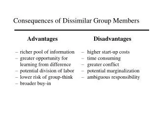
This review summarizes friction-stir welding (FSW) research at the University of Texas at El Paso (UTEP) over a period of a decade and a half, involving 18 different same materials FSW reference systems, and the FSW of 25 different, dissimilar materials systems. The FSW of dissimilar materials systems is distinguished from same materials systems FSW by the formation of complex, intercalated vortex and related flow patterns. These intercalated, lamellar-like patterns represent solid-state flow by dynamic recrystallization (DRX) which facilitates unrecrystallized, block flow in the DRX regime. Residual microindentation hardness or other hardness measured across the weld face provides comparative performance signatures for the same material FSW systems in contrast to the dissimilar FSW systems. Hardness fluctuations or complex spikes occurring in the dissimilar systems are skewed from the weld centerline and are shifted when the tool rotation direction changes or the advancing side is reversed. Keywords: Dissimilar materials FSW, Dynamic recrystallization, Optical metallography, TEM, Flow patterns
Introduction and Overview • After two decades of development, friction-stir welding (FSW) has become a viable and important manufacturing alternative or fabrication component, especially in aerospace or aeronautics applications involving aluminum alloys (Ref. 1-5). While FSW began as a joining alternative for aluminum alloys, it has now progressed to higher-temperature systems including stainless steels, titanium, and titanium alloys (Ref. 6-8). Interest has also mounted for FSW of dissimilar metals and alloys, particularly systems which are difficult or impossible to weld by conventional, thermal (or fusion) welding. FSW has also been demonstrated to be extremely effective in joining aluminum metal matrix composites (MMC’s) such as Al (6061) + 20% Al2O3 and aluminum alloy A339 containing 20% SiC a well as MMC’s welded to other dissimilar aluminum alloys (Ref. 9-11) and aluminum alloys welded to magnesium alloys by FSW(Ref. 12-14).
References • 1. I. Stol: Welding Journal, 1994, (February), 57-65. • 2. R. Irving: Welding Journal, 1998, (June), 31-35. • 3. M.R. Johnsen: Welding Journal, 1999, (February), 35-39. • 4. P.F. Mendez and T.W. Eager: Welding processes for aeronautics, Adv. Mater. Process, 2001, May, • 39-43. • 5. D. Burford, C. Widener and B. Tweedy: Advances in friction stir welding for aerospace • applications, Airframer, 2007, 14, 3-7. • 6. G. Lütjering and J.C. Williams: Titanium, 2007 Springer, New York, 109-113. • 7. D.G. Sanders, M. Ramulu and P.D. Edwards: Superplastic forming of friction-stir welds in titanium • alloy 6Al-4V: preliminary results, Materialwissenshaft und We-kstofflechnik, 2008, 39, 553-557. • 8. C. Meran, V. Kovan and A. Alptekin: Friction stir welding of A101 304 austenitic stainless steel, • Materialwissenschaff und We-kstofftechnik, 2007, 38(10), 829-835. • 9. D.J. Shindo, A.R. Rivera and L.E. Murr: J. Mater. Sci., 2002, 37, 4999-5005. • 10. R.A. Prado, L.E. Murr, K.F. Soto and J.C. McClure: Mater. Sci. Engng., 2003, A349, 156-165. • 11. M. Amirizad, A.H. Kokabi, M.A. Gharacheh, R. Sarrafi, B. Shalshi and M. Azizieh, Evaluation of • microstructure and mechanical properties in friction stir welded A356 + 15% SiC, cast composite, • Mater. Lett., 2006, 60(4), 565-568. • 12. C.G. Rhodes, M.W. Mahoney, W.H. Bingel, R.A. Spurling and C.C. Bampton: Scripta Mater., • 1997, 36, 69-73. • 13. G. Liu, L.E. Murr, C-S. Niou, J.C. McClure and F.R. Vega: Scripta Mater., 1997, 37, 355-359. • 14. Y. Li, L.E. Murr and J.C. McClure, Mater. Sci. Engng., 1999, A271, 213-223. • 15. S.H. Kazi and L.E. Murr: in Friction Stir Welding and Processing, K.V. Jata, M.W. Mahoney, R.S. Mishra, S.L. Semiatin and D.P. Field (eds.), 2001, The Minerals, Metals & Materials Soc., 139-150. • L.E. Murr, Y. Li, E.A. Trillo and J.C. McClure: Mater. Tech & Adv. Performance Mater., 2000, 15 (1), 37-48.
Fig. 1. (a) Schematic sequence (1 to 5) illustrating the FSW process and conventions: clockwise (cw) rotation (R) and head-pin (HP) or tool traverse (T) along the butted base plates (A and B). In normal operation the tool is stationary and the base plates (on a backing plate) move into the rotating tool. 4 and 5 show the weld face plane perpendicular to the x-axis and the weld surface (plane) which is perpendicular to the z-axis. (b) Schematic illustrating prominent microstructure development in the weld zone. 1 shows the original grain structure for the base plates. In 2 the grains are deformed (distorted) and dislocation density increases. 3 is a precursor to dynamic recrystallization (DRX) in 4. 5 illustrates grain growth after DRX. (c) Optical metallographic view for butted plates of Al 2024 at A and Ag at B viewed along the z-axis (5 in (a)). Weld zone region for FSW of (c) showing complex, intercalated solid-state flow. (a) is after ref. 16. (b) is after ref. 17.
Fig. 2. (a) Friction-stir welded, columnar grained aluminum 1100 alloy (R = 400 rpm, T = 1 mm/s) From ref. 18. (b) Al 2024 unwelded base plate. (c) Weld zone center after FSW of (b) at 800 rpm and 1 mm/s tool traverse speed. (d) Weld zone center for Al 2024 following FSW under liquid nitrogen to achieve a nominal temperature of -100˚C. (e) TEM view of grain structure in (d).
Fig. 3. Comparison of microindentation hardness profiles which traverse the weld center in Fig. 2(c) at room temperature and in Fig. 2(d) corresponding to FSW at -100˚C (R = 650 rpm, T = 1 mm/s). After Benavides, et al. in ref. 20.
Fig. 4. FSW of Be 62-Al 38 composite. (a) shows the weld zone (FSW), stir-affected zone (SAZ) and base plate microstructure consisting of Be particles in an aluminum matrix. (b) shows the microindentatioan hardness profile through the weld center (top-to-bottom) for an FSW tool speed of 1000 rpm (counter-clockwise) and tool traverse speed of 1 mm/s. After ref. 21.
Fig. 5. TEM views of microstructures in the unwelded Be62-Al38 base plate (a) and the weld center (Fig. 4(a)) after FSW. After ref. 21.
Overview-continued • In many systems, the welding parameters (R and T in Fig. 1(a)) may produce turbulence within the weld zone giving rise to intercalated vortices or so-called “onion ring” structures in the weld face as a consequence of the “solid fluid” motion produced by tool rotation and traverse, especially their velocities. These features are illustrated schematically in Fig. 6 which illustrates prominent flow lines associated with pin tool motion (rotation, R and traverse velocity, T) in Fig. 6(a), and the onion ring formation illustrated schematically in Fig. 6(b), which also shows a section view of the weld illustrating other, systematic structural features associtaed with weld zone flow. In most of our studies we used a hardened, ¼-20 screw as the head pin, and this design produces “fluid” turbulences different from other tool geometries. Figure 7 shows some examples of these complex flow features which are exaggerated for dissimilar materials FSW22. Figure 7(a) shows onion ring structures within the weld zone for Al 2024 welded to Al 7039 while Fig. 7(b) shows more complex features for a section view of the FSW of Al 2024 to Al 6061.
Fig. 6. Schematic views of solid-state flow and flow features associated with tool rotation (a) and traverse (b). The tool rotation illustrated is counter-clockwise (ccw).
Fig. 7. Complex, intercalation flow patterns in the weld zone for dissimilar metals FSW. (a)Onion-ring-vortex-like structure in Al 2024/Al 7039 weld zone (800 rpm – 1 mm/s, clockwise; Al 2024 advancing side) After ref. 22. (b) 3-D weld section view of intercalation flow patterns for Al 2024 welded to Al 6061 at 400 rpm (R), 2 mm/s (T). After ref. 14.
References- continued 17. L.E. Murr and C. Pizaa: Metall. & Mater. Trans. A, 2007, 38A, 2611-2628. 18. L.E. Murr, G. Liu and J.C. McClure: J. Mater. Sci., 1997, 16, 1801-1813. 19. S. Benavides, Y. Li, L.E. Murr, D. Brown and J.C. McClure: Scripta Mater., 1999, 41 (8), 809-815. 20. S. Benavides, Y. Li, and L.E. Murr: in Ultrafine Grained Materials, R.S. Mishra, S.L. Semiatin, C. Suryanarayana, N.N. Thadhani and T.C. Lowe (eds.), 2000, The Minerals, Metals and Materials Soc., 155-163. 21. F. Contreras, E.A. Trillo and L.E. Murr: J. Mater. Sci., 2002, 37, 89-99. 22. L.E. Murr, E.A. Trillo, Y. Li, R.D. Flores, B.M. Nowak and J.C. McClure: in Fluid flow phenomena in metals processing, 1999, N. El-Kaddah, D.G.C. Robertson, S.T. Johansen and V.R. Voller (eds.), The Minerals, Metals & Materials Society. 23. W. Merzkirch: Flow Visualization, 2nd Ed., 1997, Academic Press, Orlando. 24. W. Tang, X. Guo, J.C. McClure and L.E. Murr: J. Mater. Processing & Manuf. Sci., 1998, 7, 163-172. 25. L.E. Murr, Y. Li, E.A. Trillo, B.M. Nowak and J.C. McClure: Aluminum Trans., 1999, 1 (1), 141-154. 26. L.E. Murr, G. Liu and J.C. McClure: J. Mater. Sci., 1998, 33, 1243-1251. 27. L.E. Murr, G. Sharma, F. Contreras, M. Guerra, S.H. Kazi, M. Siddique, R.D. Flores, D.J. Shindo, K.F. Soto, E.A. Trillo, C. Schmidt and J.C. McClure: in Aluminum 2001-Proc. TMS 2001 aluminum automotive & joining sessions, 2001, S.K. Das, J.G. Kaufman and T.J. Lienert (eds.), The Minerals, Metals & Materials Soc. 28. J.A. Esparza, W.C. Davis and L.E. Murr: J. Mater. Sci., 2003, 38, 941-952. 29. J.A. Esparza, W.C. Davis, E.A. Trillo and L.E. Murr: J. Mater. Sci. Lett., 2002, 21, 917-920. 30. A.C. Somasekharan and L.E. Murr: J. Mater. Sci. Lett., 2006, 41, 5365-5370. 31. R.D. Flores, L.E. Murr, D.J. Shindo and E.A. Trillo: J. Mater. Processing Technol., 2000,
References- continued 32. L.E. Murr, Y. Li, E.A. Trillo, R.D. Flores and J.C. McClure: Microstructures in friction-stir welded metals, 1998, J. Mater. Process. & Manuf. Sci.,7, 146- 161. 33. A.C. Somasekharan and L.E. Murr: Mater. Character., 2004, 52, 49-64. 34. A.C. Somasekharan and L.E. Murr: in Magnesium technology, A.A. Liu (ed.), 2004, The Minerals, Metals and Materials Society, Warrendale, PA, 31-37. 35. A.C. Somasekharan and L.E. Murr: in Friction Stir Welding and Processing III, K.V. Jata (ed.), 2005, The Minerals, Metals and Materials Society, Warrendale, PA, 261-267.
Fig. 8. Complex flow patterns for dissimilar metal FSW. (a) Cu/brass, (b) Cu/Ag. Both (a) and (b) are in the weld face plane (Fig. 1(a)-4). (d) Cu/Ag (weld/surface), (d) brass/Ag (weld surface). The weld surface is perpendicular to the z-axis in Fig. 1(a)-5.
Fig. 9. Temperature-affected precipitation differences in the weld zone for FSW of Al 6061. (a) TEM image of precipitates near the top of the weld along with some residual dislocations. (b) Widmanstäten structure composed of Güinier-Preston zone precipitates and needle precipitates near the bottom of the weld.
Experimental Issues and Hardness Results • Tables 1 and 2 illustrate the FSW systems investigated at the University of Texas at El Paso (UTEP) since 1996. These systems have involved nominally 0.62 cm thick butted base plates (Fig. 1(a)) welded using a ¼-20 hardened screw slightly shorter than the base plates (~0.6 cm), and 1 to 2˚ tilt (or lead angle). Values of R and T in Tables 1 and 2 are not, as noted above, necessarily optimized. While Table 1 lists FSW of the same base materials, it is useful to have a reference for FSW for specific components composing dissimilar welds as noted in Table 2. Tables 1 and 2 also indicate the FSW parameters (pin tool rotation, R, and traverse, T). Table 3 shows the nominal composition for each of the materials investigated (Table 1).
Table 2 Dissimilar materials FSW systems and weld parameters Table 1 Same materials FSW systems and weld parameters * Columnar-grain: see Fig. 2(a). **Smaller pin tool (4.6 mm diameter, 2.58 mm long)
Table 3 Nominal chemical composition (wt.%) for FSW materials
Results - continued • Figure 10 illustrates the comparative microindentation hardness profiles in the weld face (Fig. 1(a)-4) for the first five materials in Table 1, as well as dissimilar materials combinations25. The actual weld zone extent through the weld centerline and at the weld mid-point (top-to-bottom) is indicated by arrows. For the Al 2024, 6061, and 2195, there is a notable HAZ which results from aging and precipitation variations within this zone as noted very generally for Al 6061 in Fig. 9. The very wide and relatively flat weld zone and HAZ observed for Al 2195 is the result of coherent Al2CuLi precipitate dissolution as illustrated generally in Fig. 11. The softening observed for FSW of Al 2195 in Fig. 10 results more from the loss of precipitates than DRX (Fig. 11). The difference between the FSW of Al 2195 and Al 2024 and dissimilar Al 2024/Al 2195, is the general trend toward Al 2195 within the weld zone while the edges of the HAZ for the retreating Al 2024 side and the advancing Al 2195 reflect the features of FSW for each of these component work pieces (base plates). It can be noted that there is a very similar intercalation structure for the Al 2195 and the dissimilar Al 2024/Al 2195 system as illustrated in Fig. 12.
Fig. 10. Weld zone/weld face residual (Vickers) microindentation hardness profiles for a number of same and dissimilar aluminum alloy welds. The arrows denote the weld zone boundaries at mid-weld. From ref. 25. The Al 1100 weld is for the cast, columnar-grained material shown in Fig. 2(a).
Fig. 11. Precipitation differences from the base alloy (a) and the weld zone center (b) for the FSW of Al 2195 observed by TEM. The selected area electron diffraction pattern insert in (b) is [001], representing the dark grain in the image center.
Fig. 12. Weld zone intercalation structures separating the weld zone and the SAZ for the same Al 2195 FSW in (a) and the dissimilar Al 2024/Al 2195 dissimilar FSW system in (b).
Fig. 13. Weld zone/weld face residual (Vickers) microindentation hardness profiles for a number of metal and alloy FSW systems. The Cu and brass data (a) ad (b)) is from ref. 31 while the dissimilar system FSW profiles in (c) and (d) are from ref. 32. Arrows in (d) indicate the weld zone at the weld mid point.
Fig. 14. Weld zone/weld face residual (Vickers) microindentation hardness profiles for dissimilar system FSW. (a) Ag/brass, (b) Cu/Ag, (c) Ag/Al 2024. Arrows in (c) indicate the mid-weld dimension. (d) shows an optical metallographic view for brass/Ag in the weld face plane.
Fig. 15. Complex flow and intercalation patterns for dissimilar systems FSW, All views are in the weld face plane. (a) and (b) show two similar Cu/Ag locations in the weld face plane. (c) shows an SEM view of Cu/Ag in the weld face plane.
Fig. 16. Comparison of weld face residual (Vickers) microindentation hardness profiles for a number of aluminum alloy FSW systems. From ref. 15.
Fig. 17. Comparison of weld face residual (Vickers) microindentation hardness profiles for Al 7075/Al 1100 dissimilar systems in (a) and (b), and Al 7x1x/Al/7x5x (scandium precipitation) system following FS?W. (a) and (b) are from ref. 15, (c) is from ref. 16.
Fig. 18. Comparison of residual hardness profiles for Al 6061 FSW (a), Al 6061 + 20% Al2O3 FSW (b), and Al 6061 + 20% Al2O3 with A339 + 10% SiC, and the dissimilar FSW system – Al 6061 + 20% Al2O3/A339 + 10% SiC (c). From ref. 16. Note the hardness in (b) and (c) was Rockwell E-scale.
Fig. 19. Optical metallographic images comparing the Al 6061 + 20% Al2O3 base or work-piece microstructure (a) with the structure in the weld zone following FSW (b). (c) shows the mixing of Al2O3 base or work-piece microstructure (a)with the structure in the weld zone following FSW (b). (c) shows the mixing of Al2O3 and SiC particles in the weld zone for the FSW of Al 6061 + 20% Al2O3/A359 + 20% Al2O3.
Results - continued • Magnesium alloy AM 60 is a thixomolded alloy which can have varying solid fractions of the primary phase α-Mg. Figure 20(b) compares the FSW for 3% and 18% solid fraction AM60. AZ31B and AZ91D are wrought magnesium alloy products (Table 3) which, as illustrated in Fig. 20(a), do not exhibit any precipitation hardening. Consequently, the FSW of dissimilar AZ91D/AM60D as shown in Fig. 20(c) for varying α-Mg solid fractions does not exhibit any significant weld zone variations despite the fact that DRX occurs in the weld zone, and complex, intercalation structures are created. However, even more complex, intercalation weld zone structures occur for the FSW of AZ91D/Al6061 and AZ31B/Al 6061 dissimilar systems and these exhibit very erratic hardness profiles as illustrated in Fig. 21.
a 0.76 Tool (nib) sequences showing MMC-FSW wear features for constant tool rotation of 1000 rpm and weld transverse distances noted (in meters) for specific weld speeds. (a) T=1 mm s-1 (b) T=3 mm s-1 (c) T=6 mm s-1 (d) T=9 mm s-1
Comparison of self-optimized tool shapes in the region of essentially no wear in Fig. 3. (a) and (b) correspond to linear traverse distances of 1.98 and 2.74m respectively at 1000 rpm and 6 mm s-1 weld speed. (c) and (d) correspond to linear traverse distances of 2.9 and 3.66 m respectively at 1000 rpm and 9 mm s-1 weld speed.
Fig. 20. Comparison of the weld zone/weld face residual hardness profiles for FSW of several magnesium alloy systems. (a) AZ31B (from ref. 29), (b) solid fractions of 3% and 18% AM60D (from ref. 28), (c) AZ91D/AM60D (3% and 20% solid fraction) (from ref. 33).
Fig. 21. Comparison of weld zone/weld face residual microindentation hardness profiles at different locations noted from the weld top-a, mid-section-b, and bottom-c: (a) AZ91D/Al 6061, (b) Al 6061/AZ31B, (c) AZ31B/Al 6061. From ref. 33.
Discussion and Conclusions • The salient features of FSW of dissimilar metals and alloys was illustrated and summarized at the outset in Fig. 1. Figures 3 and 4(b) also summarize the contrasting effects of softening or hardening in the weld zone implicit in the residual microindentation (or other indentation) hardness profiles in the context of FSW for the same metal or alloy system. As shown in Fig. 10, the principal difference in the FSW of the same system of metals and alloys versus dissimilar system FSW is the variation in asymmetry or the degree of symmetry with reference to the weld centerline at zero of the residual hardness profiles for dissimilar system FSW. This is apparent on comparing the Al2024/Al100, Al2024/Al6061, and Al2024/Al2195 dissimilar system hardness profiles in Fig. 10. This feature is also illustrated in Figs. 14, 16, 17(a) and (b), and Fig. 21(b) and (c). As shown in Figs. 16, and 21(b) and (c) this hardness profile asymmetry is observed irrespective of the rotation direction (cw or ccw) or the advancing side (left or right): A or B in Fig. 1(a)-1. These contrasting features are also illustrated for aluminum MMC FSW as shown in Fig. 18(c).
Conclusions - continued • Regardless of the FSW system, the fundamental process involves DRX-facilitated, solid-state flow. The material flow can produce complex, lamellar or vortex-like patterns even in the FSW of the same materials, as a consequence of intercalated regions of different hardness or degree of DRX, and especially in dissimilar system DRX where intercalation of the different base materials occurs. These complex, intercalation patterns are observed in Fig. 1(d), 7, 8, 12 and 15. Figure 8 is particularly interesting because it provides a contrast from the weld face flow (Fig. 8(a) and (b)) and mixing, to the weld surface (Fig. 8(c) and (d)), where the chuck (or tool shoulder) contributes to the DRX and flow process. These complex intercalation patterns contribute to the hardness profiles because they alter the microstructural spacing and structure which account for the hardness variations. Consequently, as shown in Figs. 13(c) and 14(a) and (b) in particular, as compared with corresponding weld face flow patterns, hardness fluctuations are related to the flow pattern structures. This feature is also implicit on examining Fig. 15 as well.
Conclusions - continued • A perusal of the diversity of FSW systems, both same and dissimilar presented in this review provides a testament to the diversity of applications, particularly commercial, for FSW. The FSW of dissimilar, light-weight systems such as Al-alloys to Mg-alloys is encouraging for a host of aerospace and automotive applications.4,5 The ability to computerize and automate the FSW process is conducive to integration into modularized manufacturing systems where dissimilar components can be joined without the distortions and complexities intrinsic to conventional fusion welding.
Acknowledgements • This research was variously supported by NASA and DoD agencies over a period of more than ten years (from 1996 to the present). Portions of this work were also supported over these years by a Mr. and Mrs. MacIntosh Murchison Chair at the University of Texas at El Paso.