Download
1 / 48
1.03k likes | 2.09k Views
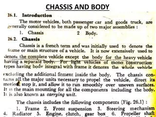
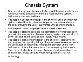
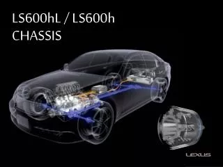
Chassis System. Chassis is the systems between the body and the road and includes frame/sub-frame, suspension (front and rear), steering system, brake system, wheels and tires

E N D
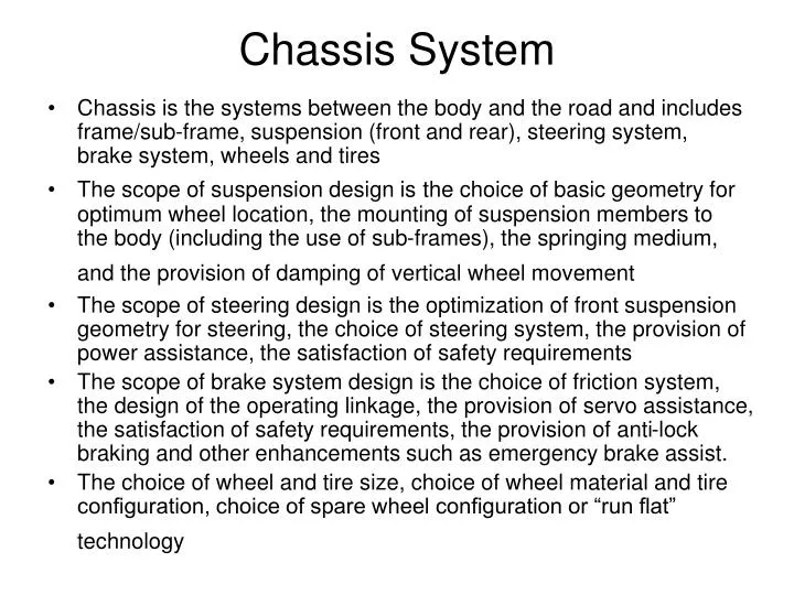
Chassis System • Chassis is the systems between the body and the road and includes frame/sub-frame, suspension (front and rear), steering system, brake system, wheels and tires • The scope of suspension design isthe choice of basic geometry for optimum wheel location, the mounting of suspension members to the body (including the use of sub-frames), the springing medium, and the provision of damping of vertical wheel movement • The scope of steering design is the optimization of front suspension geometry for steering, the choice of steering system, the provision of power assistance, the satisfaction of safety requirements • The scope of brake system design is the choice of friction system, the design of the operating linkage, the provision of servo assistance, the satisfaction of safety requirements, the provision of anti-lock braking and other enhancements such as emergency brake assist. • The choice of wheel and tire size, choice of wheel material and tire configuration, choice of spare wheel configuration or “run flat” technology
Suspension System Requirements • Allow each wheel to move vertically to provide ride comfort, while constraining its movement in other directions to maintain stability and control. Vertical wheel movement from the datum position compresses a spring keeping wheel movement within limits, although bump and rebound stops are provided should the limit – normally set by the space constraints of body design – be reached. A damper ensures that the subsequent spring movement (an oscillation) is quickly reduced to zero. • The other most important secondary aim of suspension design is to keep all four wheels as nearly upright as possible at all times, not only when traveling across uneven surfaces but also when the body rolls during cornering. A conventional car tire delivers optimum grip for cornering, braking and accelerating when it is upright. In practice it is impossible to achieve this ideal constraint without resorting to extremely costly and space-consuming measures, and current suspension systems are in most cases concerned to approach it as nearly as possible. • In some cases, as with the use of trailing arms at the rear of front-driven cars, the inevitable camber change and reduced grip during cornering is exploited as a means of reducing understeer – but overall cornering grip is also sacrificed as a result.
Suspension System Requirements • Another important requirement is that the weight of the unsprung mass i.e. wheel, tire, hub and suspension assembly at the “road” end of the spring, should be as low as possible. The lower the weight is relative to the weight of the body (the lower the ratio of unsprung to sprung mass), the less the body will react to any wheel movement, and the better the tire will be maintained in contact with the road surface, to the benefit of both ride comfort and road holding • The task of the suspension linkage which attaches each wheel to the vehicle body is to keep the wheel as nearly upright as possible in all circumstances (zero camber angle) and pointing in the desired direction (nominally parallel to the vehicle centre line, except when the front wheels are being steered), regardless of the unevenness of the road surface which causes the wheels to move vertically, and of the attitude of the vehicle body which may move in pitch, roll, and heave (pure vertical movement) according to the forces acting at its centre of gravity. • The importance of keeping the wheels as nearly vertical as possible is that this gives the tires the best chance to operate efficiently, with minimum rolling resistance. Many competition cars deliberately run positive (top-inwards) camber to achieve maximum cornering grip but the rate of tire wear and the additional rolling resistance when running in a straight line are unacceptable in most road-going cars.
Primary Functions of Suspension • Support vehicle weight. • Keep the tires in contact with the road. • Control vehicle’s direction of travel • Maintain correct wheel alignment, important in vehicle handling • Reduce effect of shock loads with the use of springs, dampers and bushings • Maintain correct vehicle ride height
Top Mount Bump Stopper Spring Strut Rubber boot Lock Nut Link Camber Bolt Wheel Mounting Bolt Stabilizer Bar Wheel Cap Rubber Bushes Drive Shaft / Spindle Wheel Bearing Lower Link Heat Shield for Ball Joint (To protect from Brake Disc heat) Brake Disc Lower Ball Joint Tyre Wheel Rim McPherson Strut Suspension
Features of McPherson Strut • Upper control arm in double wishbone is eliminated • Provides anchoring of tie rod on knuckle • Combines the following parts into one assembly to provide wheel control • Spring Seats • Springs, Bump stoppers • Rebound Stopper • Link for mounting Stabilizer Bar • Lower the Forces on BIW-Mountings • Provide Better Space at the side to mount transverse Engine & Gear box • Better Space for Front Crash Members & Crumple zones
Advantages of McPherson Strut Disadvantages • Less favorable kinematic characteristics • Forces & vibrations transferred to inner wheel-arch panel which is relatively elastic • Difficult to insulate against road noise • Friction between piston rod & guide impairs the springing effect • Critical to package [Gaps between Tyre & damper, Springs & Wheel-arch] • Ground Clearance critical • Advantages • Combination of several parts into one assembly • Upper transverse link replaced by top mount • Occupies less space • Transverse engine mounting possible • More space for front crumple zone
Tyre Stabilizer Bar Top Mount Upper Control Arm Upper Ball Joint Brake-Rod Rubber Bushes Brake Disc Steering Gear Knuckle Spring& Damper Wheel Mounting Bolt Lower Link Tie Rod Lower Ball Joint Double Wishbone Suspension
Features of SLA or Double Wishbone • Has 2 control arms (upper & lower) connected to the steering knuckle by ball joints (UBJ & LBJ) • Upper control arm in double wishbone is shorter than lower arm which helps control the camber angle to desired level during body roll • Spring, shock and anti-roll bar are attached to LCA • Steering arm is attached to the knuckle
Advantages of Double Wishbone Suspension • Disadvantages • More complex than McPherson Strut • Short spindle SLAs tends to require stiffer bushings at the body, as the braking and cornering forces are higher. Also they tend to have poorer kingpin geometry, due to the difficulty of packaging the upper ball joint and the brakes inside the wheel. • Long spindle SLAs tend to have better kingpin geometry, but the proximity of the spindle to the tire restricts fitting oversized tires, or snow chains. The location of the upper ball joint may have styling implications in the design of the sheetmetal above it. • Advantages • Kinematics can be controlled easily • Provides good camber compensation during vertical movement • Pitching movements can be balanced i.e anti-dive, anti-squat possible • Toe-in, Camber & Track change can be controlled optimally due to variety of control parameters
Front Suspension Parts Sub-frame ARB Steering Tie-rods Corner Module Subframe Wheel rim Tyre Drive Shaft / Bearing Knuckle Strut / Damper Suspension Bush Lower Link Ball Joint Spring
E D Welded Rigid Connection E S T P B D S TA CB TA B TA : Trailing Arms CB : Cross Beam B : Pivot Bushes S : Coil Spring D : Dampers E : Top Mount T : Torsion bar P : Panhard Rod P Twist Beam Rear Suspension
Features of Twist Beam Suspension • Very compact package • Inexpensive to manufacture, assemble/disassemble. • Eliminates several parts: control arms, anti-roll-bar, etc. • Twist axle acts as a anti-roll-bar • High stresses in the welds
Advantages of a Twist Beam Suspension • Disadvantages • Exhibits compliance Oversteer tendency • Torsion & Shear stress in Cross member • High stress in weld seams • Advantages • Whole axle easy to assemble & dismantle • Requires very little space, easy to package spare tire, fuel tank, etc. • Spring-Damper assembly is easy to fit. • Control Arms & Rods are eliminated. • Wheel to Spring Damper ratio favorable. • Less unsprung mass • Cross member acts as a anti-roll-bar • Negligible toe-in & track change • Low camber change under lateral forces.
Twist Beam Rear Suspension Parts Packaging Unitized Bearing Twist Beam Suspension Bush Tyre Twist Beam Module Strut / Damper Wheel rim Drum Drum Brake Spring
3-Link Rear Suspension Top Mount Coil Spring Damper Sub-frame Longitudinal Link Transverse Links Pivot Bushings
3-Link Rear Suspension Parts Subframe with Multilink Suspension Unitized Bearing Multi-Link Suspension Suspension Bush Strut / Damper Multi-Link Suspension Drum Drum Brake Tyre Spring
Features of 3-Link Rear Suspension • Relatively expensive • Requires more space • Easier to control wheel movement with 3 links • Longitudinal link picks up longitudinal loads • Transverse links pick up lateral loads
Advantages of 3-Link Rear Suspension • Advantages • Pitching movements can be balanced i.e 100% anti-dive, anti-squat possible • Toe-in, camber, track change can be controlled optimally due to variety of control parameters • Disadvantages • Costly as compared to twist beam and other suspensions due to increased number of components, links, bushings & bearings • Higher production & assembly costs • Higher degree of tolerance control required to maintain geometry
Hotchkiss Rear Suspension Tyre Parabolic Leaf Spring Conventional Leaf Spring Wheel rim Hotchkiss Suspension Hotchkiss Suspension U Bolt Suspension Bush Shackle ARB Bush
Features of Hotchkiss Rear Suspension • Simple in design • High weight • Easy to assemble • Provides good pay load carrying capacity • Robust in design
Advantages of Hotchkiss Rear Suspension • Advantages • Simple with very few parts • Easy to manufacture & assemble • Robust design • High load carrying capacity • Disadvantages • High weight of suspension i.e high unsprung mass. • Occupies More Space than other suspension types
Wheel Movements Controlled by Suspension • Jounce & Rebound • Roll • Toe in/Toe out • Left or Right Steer • Camber • Spin
z z Rear View y y Spring Compression At Ride Height In Jounce Spring Extension Axle/Vehicle Jounce & Rebound At Ride Height In Rebound
z z Rear View y y Spring Compression At Ride Height Axle Roll Spring Compression At Ride Height Body Roll Axle/Vehicle Roll
z y Wheels with no Camber Wheels with Camber Rear View Wheel Camber
x Top View y Wheel Toe-out Wheel Toe-in Wheel Toe in/Toe out
x Top View y Wheel LH Steer Wheel RH Steer Wheel Steer
z • Note: • Wheel at original position (pink) • Wheel in jounce (blue) • Original control arms (solid) • Control arms in jounce (dotted) • Note wheel camber y Wheel Assembly In Jounce Upper Ball Joint Upper Control Arm Wheel Assembly Ride Height Body Pivot Lower Ball Joint Rear View Lower Control Arm Suspension Geometry in Wheel Jounce
z • Note: • Wheel at original position (pink) • Wheel in jounce (blue) • Original control arms (solid) • Control arms in jounce (dotted) • Note wheel camber y Wheel Assembly In Jounce Upper Ball Joint Upper Control Arm Wheel Assembly Ride Height Body Pivot Lower Ball Joint Rear View Lower Control Arm Suspension Geometry in Wheel Rebound
z • Note: • Wheel at original position (pink) • Wheel in jounce (blue) • Original tie rod (solid) • Tie rod in jounce (dotted) • Note geometry error Rear View y Steering arm Ball joint New path for steering arm ball joint New position for body ball joint Tie Rod Ideal path for steering arm ball joint Ideal Location for body ball joint Steering Geometry Error in Wheel Jounce
z Ball joint Pulled in Short Tie Rod Path Ball joint Pulled out y Steering arm ball joint at jounce jounce Steering arm ball joint at ride height Long Tie Rod Path Center for Short tie rod Ideal center for tie rod on body Ideal path Rear View Center for long tie rod Steering Geometry Error in Wheel Jounce
z y Ball joint Pulled out New Path Center above Ideal jounce Steering arm ball joint at jounce New Tie Rod Rear View Ideal Tie Rod Steering arm ball joint at ride height Ideal center for tie rod on body Ideal path Steering Geometry Error in Wheel Jounce
Suspension Roll Center • Roll center is defined as a location at which lateral forces developed by the wheels are transferred to the sprung mass • Each suspension has a roll center • Lateral forces can be applied to the sprung mass at the roll center without causing suspension roll • Each suspension has a roll axis about which un-sprung mass rolls when a pure moment is applied • Vehicle roll axis is the line joining the roll centers of the front and rear suspensions
Roll Centers z x
Fy Upper Link UL Top View Lower Link LL FyUL FyLL b a Side View FyLL/FyUL = b/a FyLL+FyUL = Fy Roll Center for 4-Link Solid Axle y x z x
Track Bar Top View Side View Roll Center for 3-Link Solid Axle y x z x
Roll Axis Side View Roll Center for Hotchkiss z x
z Rear View y Roll Center for Positive Swing Arm SLA FU Fy FL Fy
Assignment • Determine roll center for your suspension • Determine suspension envelope in y-z plane for your suspension