Download
1 / 17
350 likes | 1.83k Views
Pneumatics Module 9 . Time delay valve. Demonstrate an understanding of the different types of time delay valves. Identify the normally closed time delay valve. Identify the main parts of the time delay valve.

E N D
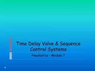
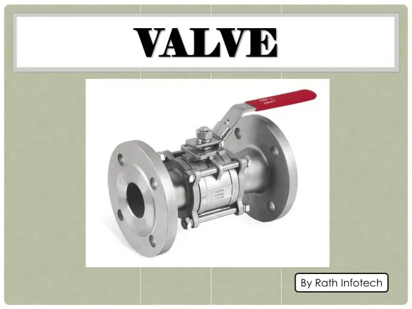
Pneumatics Module 9 Time delay valve
Demonstrate an understanding of the different types of time delay valves. • Identify the normally closed time delay valve. • Identify the main parts of the time delay valve. • Draw a pneumatic circuit diagram that consists of a time delay valve, normally closed. • Simulate pneumatic circuit that consists of a time delay valve using Fluid SIM software. • Build a pneumatic circuit that consists of a time delay valve as per specific requirements. Objectives
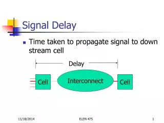
Pneumatic time elements can be formed very simply from combinations of three valves: directional control valve, throttle valve and reservoirs. Time delay valve
Time delay valve is used to delay the output signal. The time delay valve is actuated by a pneumatic signal through the tank after a preset time delay has elapsed. The returned to the normal position via return spring when the signal is terminated. function
Time Delay Valve N/C symbols Time Delay Valve N/O
The time delay valve is a combination of a 3/2 way valve, one way flow control valve and air reservoir. The 3/2 way valve can be normally open or normally closed. The delay time is generally ranging between (0-300) seconds for both types of valves (normally opened and normally closed). By using additional reservoirs, the delaying time can be extended. The type of the time delay valve whether normally opened or normally closed is determined according to the type of the 3/2 way valve if it is N/O or N/C. design
Design 3/2 way valve N/C 3/2 way valve N/O
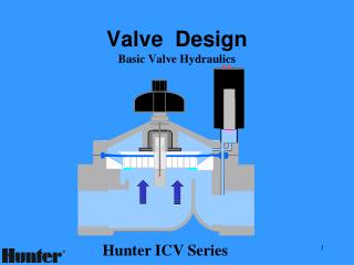
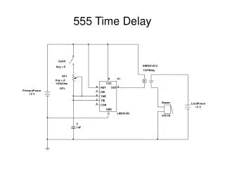
The following operational principle applies for a time delay valve in normally closed position. The compressed air is supplied to the valve at connection 1. The control air flows into the valve at 12 through a one way flow control valve and depending on the setting of the throttling screw, a greater or lesser amount of air flows per unit of time into the air reservoir, when the necessary control pressure has built up in the air reservoir, the pilot control of the 3/2 way valve is moved downwards. This blocks the passage from 2 to 3. The valve disc is lifted from its seat and thus air can flow from1 to 2 . The time required for pressure to build up in the air reservoir is equal to the control time of the valve. Principle of operation
Un-actuated Position Principle of operation • Actuated Position
The time response and behavior of the pneumatic circuits with time delay valves varies according to the following two factors: 1) Type of 3/2 way valve if it is N/O or N/C. 2) The direction of the check valve in the one way flow control valve. (Direction of throttling). Time behavior of circuits with time delay valves
A double acting cylinder is used to press glued components together. Upon operation of a push button, the clamping cylinder extends. Once the fully advanced position is reached, the cylinder is to remain for a time of T = 6 seconds and then retract to the initial position automatically. The cylinder retraction is to be adjustable. A new start cycle is only possible after the cylinder has fully retracted. Practical task 1
The limit switch 1S2 must be actuated as a start condition. And by pressing the push button switch 1 S1, two signals will reach the two pressure valve 1 V1, which in turn will pass the pressure signal to port 14 of the 5/2 way valve 1V3. The valve 1V3 reverses resulting in advancing the piston rod of the cylinder 1A with a specific speed according to the setting of the one way flow control valve 1 V4. When the cylinder reaches the forward end position, it will activate the limit switch 1S3. The air reservoir of the time delay valve starts filling up, and after the adjusted time elapsed, the valve 1V2 will pass the pressure signal to port 12 of the valve 1V3. The valve 1V3 reverses, and the piston rod retracts to the initial position with adjusted speed determined by the one way flow control valve 1V5. Solution description


![[10001] Time-delay Information Blockette (18 bytes)](https://cdn4.slideserve.com/9252579/10001-time-delay-information-blockette-18-bytes-dt.jpg)