Download
1 / 1
10 likes | 91 Views
FOCMEC. I. SOLA. AMT. KAT. SMO. N =. 36. N = 38. N =. 16. 5.0. 5.0. 3.0. Frequency [Hz]. 3.0. 1.8. 1.8. 1. 2. 1. 2. Z. N. E. Z. N. E. 6. 2. 8. 8. 6. 4. 6. 8. 2. 4. 2. 4. 6. 6. band-pass filter 1.2 -5.0 Hz. 2. 2. 8. 8. 6. 4. 2. 4. 8. 4. Time [s].

E N D
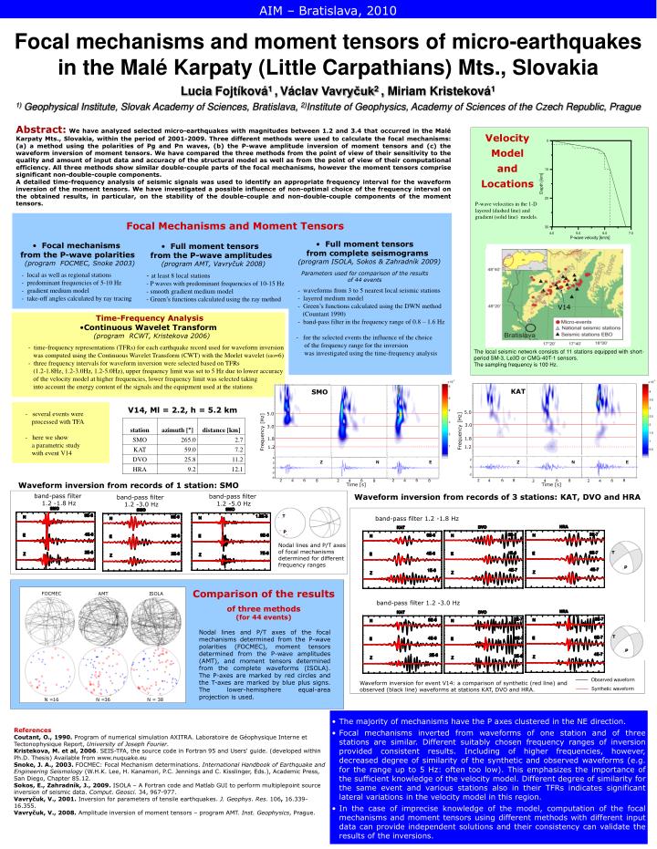
FOCMEC I SOLA AMT KAT SMO N = 36 N = 38 N = 16 5.0 5.0 3.0 Frequency [Hz] 3.0 1.8 1.8 1.2 1.2 Z N E Z N E 6 2 8 8 6 4 6 8 2 4 2 4 6 6 band-pass filter 1.2 -5.0 Hz 2 2 8 8 6 4 2 4 8 4 Time [s] band-pass filter 1.2 -3.0 Hz Time [s] Observed waveform Synthetic waveform AIM – Bratislava, 2010 Focal mechanisms and moment tensorsof micro-earthquakesin the Malé Karpaty (Little Carpathians) Mts., Slovakia Lucia Fojtíková1 ,Václav Vavryčuk2, Miriam Kristeková1 1) Geophysical Institute, Slovak Academy of Sciences, Bratislava, 2)Institute of Geophysics, Academy of Sciences of the Czech Republic, Prague Abstract:We have analyzed selected micro-earthquakes with magnitudes between 1.2 and 3.4 that occurred in the Malé Karpaty Mts., Slovakia, within the period of 2001-2009. Three different methods were used to calculate the focal mechanisms: (a) a method using the polarities of Pg and Pn waves, (b) the P-wave amplitude inversion of moment tensors and (c) the waveform inversion of moment tensors. We have compared the three methods from the point of view of their sensitivity to the quality and amount of input data and accuracy of the structural model as well as from the point of view of their computational efficiency. All three methods show similar double-couple parts of the focal mechanisms, however the moment tensors comprise significant non-double-couple components. A detailed time-frequency analysis of seismic signals was used to identify an appropriate frequency interval for the waveform inversion of the moment tensors. We have investigated a possible influence of non-optimal choice of the frequency interval on the obtained results, in particular, on the stability of the double-couple and non-double-couple components of the moment tensors. Velocity Model and Locations P-wave velocities in the 1-D layered (dashed line) and gradient (solid line) models. Focal Mechanisms and Moment Tensors • Full moment tensorsfrom complete seismograms • (program ISOLA, Sokos & Zahradník 2009) • Parameters used for comparison of the results • of 44 events • - waveforms from 3 to 5 nearest local seismic stations • - layered medium model • - Green’s functions calculated using the DWN method • (Countant 1990) • - band-pass filter in the frequency range of 0.8 – 1.6 Hz • - for the selected events the influence of the choice • of the frequency range for the inversion • was investigatedusing the time-frequency analysis • Focal mechanisms from the P-wave polarities • (program FOCMEC, Snoke 2003) • - local as well as regional stations • - predominant frequencies of 5-10 Hz • - gradient medium model • - take-off angles calculated by ray tracing • Full moment tensors from the P-wave amplitudes • (program AMT, Vavryčuk 2008) • - at least 8 local stations • - P waves with predominant frequencies of 10-15 Hz • - smooth gradient medium model • - Green’s functions calculated using the ray method V14 • Time-Frequency Analysis • Continuous Wavelet Transform • (program RCWT, Kristekova 2006) • - time-frequency representations (TFRs) for each earthquake record used for waveform inversion • was computed using the Continuous Wavelet Transform (CWT) with the Morlet wavelet (ω0=6) • - three frequency intervals for waveform inversion were selected based on TFRs • (1.2-1.8Hz, 1.2-3.0Hz, 1.2-5.0Hz),upper frequency limit was set to 5 Hz due to lower accuracy • of the velocity model at higher frequencies, lower frequency limit was selected taking • into account the energy content of the signals and the equipment used at the stations The local seismic network consists of 11 stations equipped with short-period SM-3, Le3D or CMG-40T-1 sensors. The sampling frequency is 100 Hz. - several events were processed with TFA - here we show a parametric study with event V14 V14, Ml = 2.2, h = 5.2 km Frequency [Hz] Waveform inversion from records of 1 station: SMO band-pass filter 1.2 -1.8 Hz Waveform inversion from records of 3 stations: KAT, DVO and HRA T band-pass filter 1.2 -1.8 Hz P Nodal lines and P/T axes of focal mechanisms determined for different frequency ranges T P Comparison of the results of three methods(for 44 events) band-pass filter 1.2 -3.0 Hz Nodal lines and P/T axes of the focal mechanisms determined from the P-wave polarities (FOCMEC), moment tensors determined from the P-wave amplitudes (AMT), and moment tensors determined from the complete waveforms (ISOLA). The P-axes are marked by red circles and the T-axes are marked by blue plus signs. The lower-hemisphere equal-area projection is used. T P Waveform inversion for event V14: a comparison of synthetic (red line) and observed (black line) waveforms at stations KAT, DVO and HRA. • The majority of mechanisms have the P axes clustered in the NE direction. • Focal mechanisms inverted from waveforms of one station and of three stations are similar. Different suitably chosen frequency ranges of inversion provided consistent results. Including of higher frequencies, however, decreased degree of similarity of the synthetic and observed waveforms (e.g. for the range up to 5 Hz: often too low). This emphasizes the importance of the sufficient knowledge of the velocity model. Different degree of similarity for the same event and various stations also in their TFRs indicates significant lateral variations in the velocity model in this region. • In the case of imprecise knowledge of the model, computation of the focal mechanisms and moment tensors using different methods with different input data can provide independent solutions and their consistency can validate the results of the inversions. References Coutant, O., 1990. Program of numerical simulation AXITRA. Laboratoire de Géophysique Interne et Tectonophysique Report, University of Joseph Fourier. Kristekova, M. et al, 2006. SEIS-TFA, the source code in Fortran 95 and Users‘ guide. (developed within Ph.D. Thesis) Available from www.nuquake.eu Snoke, J. A., 2003. FOCMEC: Focal Mechanism determinations. International Handbook of Earthquake and Engineering Seismology (W.H.K. Lee, H. Kanamori, P.C. Jennings and C. Kisslinger, Eds.), Academic Press, San Diego, Chapter 85.12. Sokos, E., Zahradník, J., 2009. ISOLA – A Fortran code and Matlab GUI to perform multiplepoint source inversion of seismic data. Comput. Geosci. 34, 967-977. Vavryčuk, V., 2001. Inversion for parameters of tensile earthquakes. J. Geophys. Res. 106, 16.339-16.355. Vavryčuk, V., 2008. Amplitude inversion of moment tensors – program AMT. Inst. Geophysics, Prague.