Download
1 / 23
230 likes | 475 Views
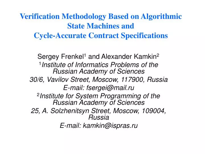
Verification Methodology Based on Algorithmic State Machines and Cycle-Accurate Contract Specifications. Sergey Frenkel 1 and Alexander Kamkin 2 1 Institute of Informatics Problems of the Russian Academy of Sciences 30/6, Vavilov Street, Moscow, 117900, Russia E-mail: fsergei@mail.ru

E N D
Verification Methodology Based on Algorithmic State Machines andCycle-Accurate Contract Specifications Sergey Frenkel1 and Alexander Kamkin2 1Institute of Informatics Problems of the Russian Academy of Sciences 30/6, Vavilov Street, Moscow, 117900, Russia E-mail: fsergei@mail.ru 2Institute for System Programming of the Russian Academy of Sciences 25, A. Solzhenitsyn Street, Moscow, 109004, Russia E-mail: kamkin@ispras.ru
Design Steps Currently above DESIGN PROCESS are implemented in the following steps: Architectural Synthesis Input: behavioral description, usually by some Hardware Design Languages (HDL, e.g.,Verilog, VHDL), or by a system ones (e.g.,Csystem, some Petri net based languages, etc). Output: generated architecture for design at RTL, namely: data path (interconnection of adders, multipliers, etc), FSM model of control unit (signals to control data path), scheduling and binding Logic Synthesis Input: RTL description (HDL). Output: converts into network of logic primitives (depending on design style). Physical Design: Out of our consideration Our tool can provide the input for logic synthesis (in CADENCE, SYNOPSIS, MENTOR GRAPHIC) automatically. One of important contributions of our proposal could be a new bridge between Architectural (System) synthesis and Logic one, also taking into account some requirements to Fault-tolerant design.
Challenges of current design verification methodology 50-80% of ASIC / IP / SoC design effort goes to verification, whathas effects on Schedule, Cost, Quality. Due to chip complexity this becomes more and more difficult, namely: • complexity of formal verification is prohibited for many real-life designs; • simulation is slow, requires billions of vectors for large designs, and exhaustive simulation is infeasible; • the verification tools and methods need to scale well, and be able to support efficient debugging, have to allow for ongoing changes in the specification and the design; • the methodology must be flexible enough to permit new design features, such as soft error detection, including fault latency and self - healing analysis.
Total design cost reducing A work of a designer is resulted in two or three activities and human/equipment resources which have been spent for one of them should be kept back in another.
Two ways of Design Validation Formal Verification Validation ~ Verification Verification via Simulation
Possible combination of two approaches • a “mechanical” combination of the verification techniques: part of design is verified by simulation, while another by a formal method; • by using a semi-formal specification for implementation and establishment of properties for the formal verification.
Semi-Formal Verification Informal specification Semi-Informal Specification: Formalized Application- Specific System Description language+ Informal Requirements Specification Semi-formal Formal Verification Simulation Application Specific Languages Verilog, VHDL, Cycle-Accurate Contract Specification Language Fail, Pass
Verification via Model Checking FINITE-STATE SYSTEM PROPERTY TO VERIFY propagates sets of states, not individual trajectories MODEL CHECKING PROGRAM PROPERTY IS TRUE OR A COUNTER EXAMPLE • temporal logic specifications
pre(A, 1) post(A, 1) A1 A1 A1 … … … … … … pre(A, N) post(A, N) AN AN AN Cycle-Accurate Contract Specifications Operation Contracts of stages Contract of operation Operations Contracts of stages Contracts of operations pre(A)
A1 A2 … AN B1 B2 … BN Idea of the Method post(A, 2) post(B, 1) OperationA OperationB Test Oracle … Time 1 2 3
A —stage B —branch —fork —join C Branching and Other Features
Algorithmic State machine (ASM) An Algorithmic State Machine (ASM) is the directed connected graph containing an initial vertex (Begin), a final vertex (End) and a finite set of operators and conditional vertices. The operators and conditional vertices have only one input, the initial vertex has no input. Initial and operator vertices have only one output, a conditional vertex has two outputs marked by "1“ and "0". A final vertex has no outputs. Each operator include some body in a pseudocode, and its execution takes a clock of the target system time The following are the major steps in the ASM methodology: • Describe the target system algorithm by ASM chart (using a pseudocode), • Design the datapath based on the ASM chart, • Design the control logic based on the detailed ASM chart, If followed correctly, the ASM method produces a hardware design in a systematic and logical manner • Very robust and easily modified • Refined through design iterations
About ASM formalities • A possibility to use some ASM-based formalized verification is due to some formal rules, used for ASM flowchart construction. Namely, to provide this unique correspondence between the ASM flowchart and a target data path and control unit it is enough that a synthesis algorithm would obey the following rules: • State boxes should contain only register statements, control signals in parentheses; • All operations within a state box should be concurrently executable in one clock cycle. • If the operations in two consecutive state boxes can be executed in the same clock cycle, then these two state boxes can be combined into one state box. • For each register-transfer statement, there must be a path between the source and destination registers. • The description contains the ordering of microoperations, namely, each of rectangle take one clock for its execution.
ASM Example Let us an operator Yb be implemented. The sequence of the actions after Yb can be represented by ASM as following: The operator Y3 is executed after Yb when x1x4x3=1,Y1 is executed afterYb when x1x’3=1, Y5 is excuted after Yb when x1x4x’3=1 or x’1=1, that is: Yb→ x1x4x3Y3 + x1x4x'3Y5+ x1x'4Y1+ x'1Y5
System/Logic Designby Abelite(Prof. Samary Baranov, Holon Institute of Technology, Israel) ASM-description I1 I2 In FSM Micro operations FSM Joint ASM FlowChart RTL (VHDL) Design Tools (SYNOPSIS, CADENCE
ASM-based verification (contd.) Translated ASM model is converted automatically in VHDL/VERILOG test bench of a behavior model of the target system, which is simulated by a well known tool, e.g. by ModelSim (Mentor Graphic). The detected output is the desirable behavior of the target system which should compare with the result of the structural synthesis , implemented by ABELITE (“Actual output”).This actual output is also the result of simulation by the same tool, e.g. ModelSim.
ASM-specified Model Checking • a1 a10 1 y7y8y9y10y11y12 1 Micro Instructions: • a2 a3 1 y2y3 2 Y1 = y1 • a3 a1 1 y4 3 Y2 = y2 y3 • a4 a2 1 y1 4 Y3 = y4 • a5 a4 1 y4 5 Y4 = y5 y3 • a6 a7 1 y4 6 Y5 = y6 y3 • a7 a8 1 y1 7 Y6 = y7 y8 y9 y10 y11 y12 • a8 a5 1 y5y3 8 • a9 a6 1 y6y3 9 Micro Operations: • a10 a9 1 y1 10 y1 : v:=(v+c_in)mod 2 • y3 : c_out:=v&c_in • y4 : c_in:=c_out • y5 : b1:=v • y6 : b0:=v • y7 : b0:=0 • y8 : b1:=0 • y9 : b2:=0 • y10 : c_in:=1 • y11 : c_out:=0 • y12 : v:=0
Model Checking (contd.) Conditinos of Natural Ordering of Counting SPEC AG (((bit0=0)&(bit1=1) &(bit2=0)) ->AX((bit0=1)&(bit1=1)&(bit2=0))) SPEC AG (((bit0=0)&(bit1=1) &(bit2=0)) ->AX((bit0=1)&(bit1=1)&(bit2=1)))